
Three dimensional visual programming interface for a network of devices

a network of devices and programming interface technology, applied in the field of graphical user interfaces, can solve problems such as difficulty in basic tasks such as identifying a particular object within the environment, and inability to easily ascertain the functions of objects and logical connections between objects, and achieve the effect of easy programing and understanding

Pending Publication Date: 2018-01-04
AUTODESK INC
View PDF11 Cites 8 Cited by
  • Summary
  • Abstract
  • Description
  • Claims
  • Application Information

AI Technical Summary

Benefits of technology

The disclosed technique allows users to easily program and understand the functions of a network of physical objects through a 3D visual programming interface. Its technical effects include simplifying programming and enhancing understanding of complex functions.

Problems solved by technology

However, such conventional tools generally fail to provide information about a particular object's spatial relationship to other objects within a given networked environment.
As a result, basic tasks, such as identifying a particular object within the environment, may be difficult.
Also, when using conventional 2D interface environments, the functions of the objects and logical connections between the objects are not easily ascertainable to a user and require additional investigation and inquiry by the user.
Further, programming or modifying the various functions that can be implemented by different objects within the networked environment and / or the connections between different objects within the networked environment can be challenging for users with limited programming skills.
Finally, with conventional 2D interface environments, after executing the programming functions of the connected objects at runtime, understanding how each object operates within the total context of the networked environment can be quite difficult for users.
Thus, if various objects do not operate / function correctly or as intended, inspecting or debugging those objects and / or the connections between the objects can be impractical or even impossible for most users.

Method used


Image

  • Three dimensional visual programming interface for a network of devices
  • Three dimensional visual programming interface for a network of devices
  • Three dimensional visual programming interface for a network of devices

Examples


Embodiment Construction

[0022]In the following description, numerous specific details are set forth to provide a more thorough understanding of the present invention. However, it will be apparent to one of skill in the art that the present invention may be practiced without one or more of these specific details. In other instances, well-known features have not been described in order to avoid obscuring the present invention.

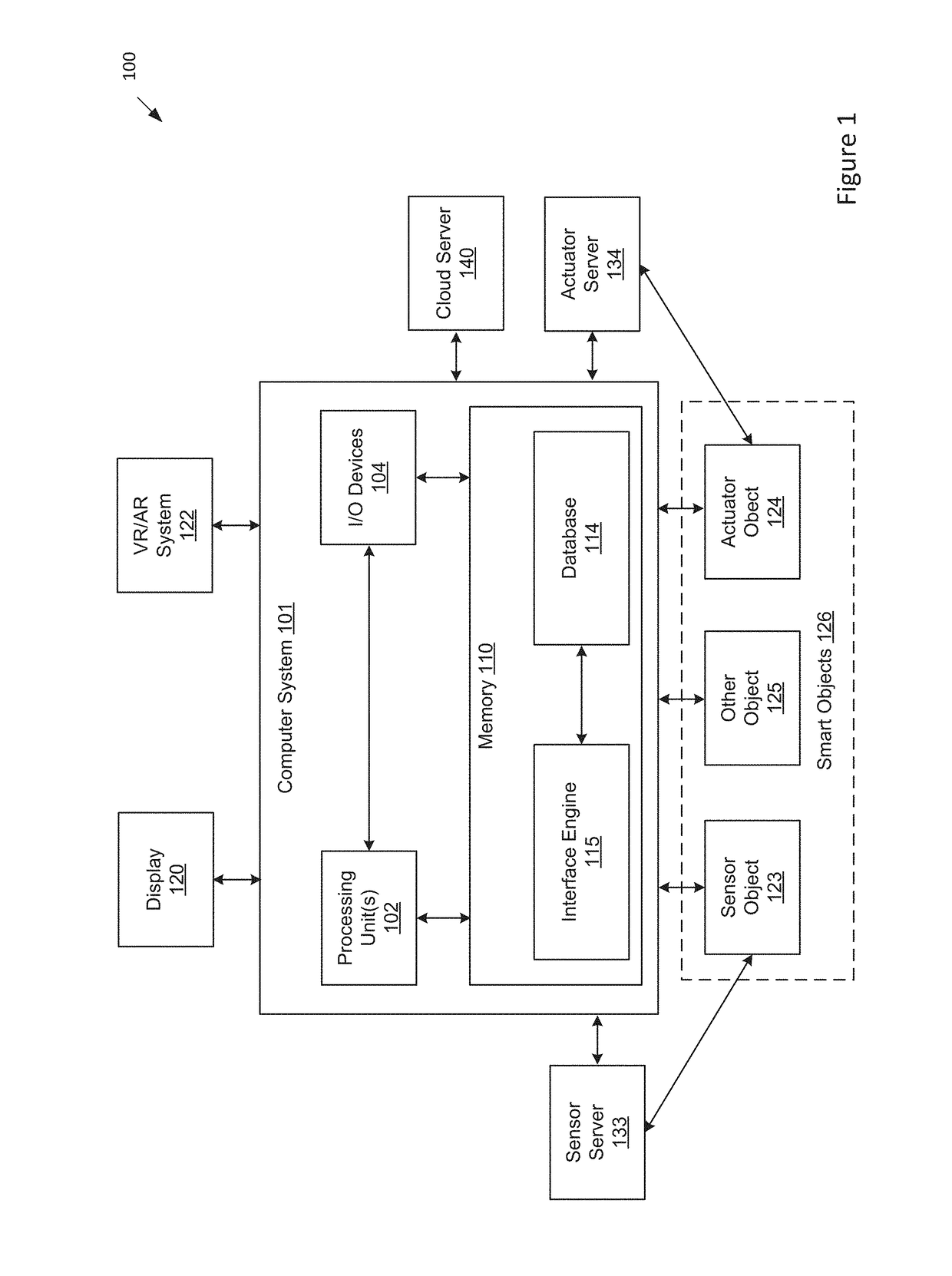
[0023]The following description is divided into four sections. Section I describes an architecture of a 3D visual programming system within which embodiments of the present invention may be implemented. Section II describes systems and methods for displaying a 3D virtual environment comprising virtual objects for representing a real-world environment comprising physical objects. Section III describes systems and methods for authoring logic nodes (representing functions) and links between logic nodes within the 3D virtual environment and executing the logic nodes to implement the functio...


PUM


Abstract

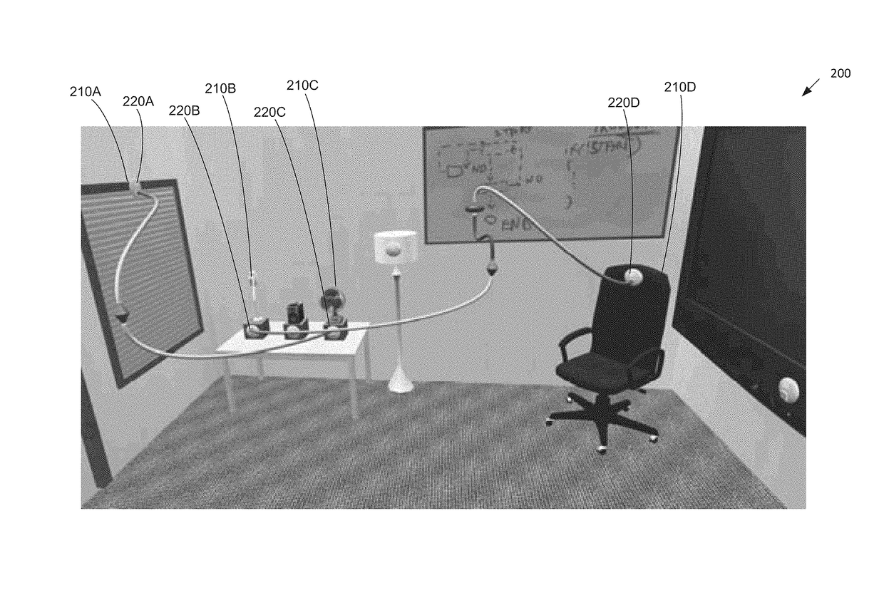
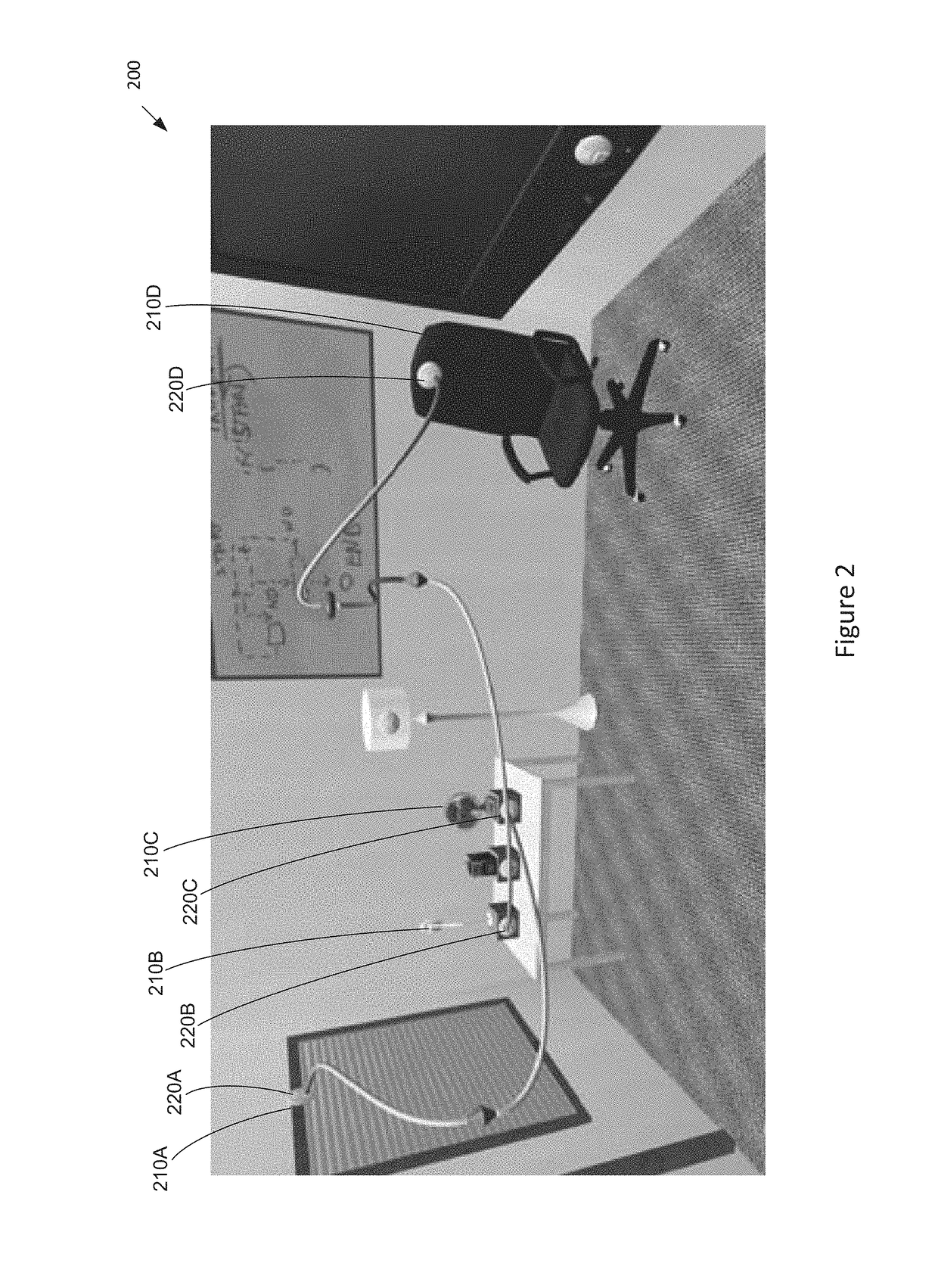
Approaches for generating virtual representations of smart objects in a 3D visual programming interface. The interface displays a 3D virtual environment containing virtual objects that represents a real-world environment containing smart objects. The 3D virtual environment displays virtual objects in a manner that is spatially accurate relative to the physical objects in the real-world environment. For each virtual object representing a physical object, a logic node (port node) is displayed, the port node representing the set of functions associated with the physical object. The interface enables users to create, delete, or modify different types of logic nodes (representing functions) and create, delete, or modify links (representing data connections) between logic nodes within the 3D virtual environment. The authoring of the logic nodes and links produces an executable program. Upon executing the program, data flows between the logic nodes are visually represented as particles moving between the logic nodes.

Description

CROSS-REFERENCE TO RELATED APPLICATIONS[0001]This application claims the benefit of U.S. provisional patent application titled, “VISUAL PROGRAMMING INTERFACE FOR AUTHORING AND VIEWING A NETWORK OF DEVICES,” filed on Jul. 1, 2016 and having serial number 62 / 357,856. The subject matter of this related application is hereby incorporated herein by reference.BACKGROUND OF THE INVENTIONField of the Invention[0002]Embodiments of the present invention relate generally to a graphical user interface (GUI) and, more specifically, to a three dimensional (3D) visual programming interface for a network of devices.Description of the Related Art[0003]The ubiquity of computing devices has led to a proliferation of connected network devices, such as smart objects. This manifestation, known colloquially as the Internet of Things (IoT), is growing exponentially with over 20 billion objects expected to be connected by 2020. Taking full advantage of this network of smart objects requires tools that allow...

Claims


Application Information

Patent Timeline
IPC IPC(8): G06F3/0481H04L12/24
CPCH04L41/22G06F3/04815G06F3/011
Inventor ENS, BARRETTANDERSON, FRASERFITZMAURICE, GEORGEGROSSMAN, TOVI
Owner AUTODESK INC
Learn More