
Process for the synthesis of ammonia

a technology of ammonia and synthesis, which is applied in the direction of chemistry apparatus and processes, chemical production of bulk chemicals, energy input, etc., can solve the problems of less hydrocarbon feedstock available, consumption of fuel and related costs, pollution of atmosphere, etc., and achieve the effect of increasing the reforming capacity, and reducing the amount of ammonia

Active Publication Date: 2018-01-04
CASALE SA
View PDF5 Cites 1 Cited by
  • Summary
  • Abstract
  • Description
  • Claims
  • Application Information

AI Technical Summary

Benefits of technology

This patent is about a method for increasing the production of syngas in a way that does not require adding more fuel or increasing emissions in the atmosphere. It also reduces the need for additional equipment and allows for easier revamping of existing plants. The method involves heating the mixed feed in a heat exchanger and using a pre-reformer to increase the capacity of the plant. Finally, adding a new synthesis reactor can also be an effective way to increase production. Overall, the method improves efficiency and reduces costs for producing syngas.

Problems solved by technology

Combustion in a reforming furnace has the disadvantages of: polluting the atmosphere, in particular due to emissions of carbon dioxide (CO2) and nitrogen oxides (NOx); consumption of a fuel and related cost; less hydrocarbon feedstock available as process gas when the same is also used as a fuel.
Furthermore, revamping of a fired equipment is expensive, which means that a revamping to increase capacity of a front end including a fired reformer is costly.
This preheating is achieved in the feedstock pre-heater coils in the convection section and increases the fuel consumption of the reformer.
Moreover, a GHR is expensive due to the use of a hot source having a very high temperature and normally containing significant amounts of carbon monoxide (CO) leading to risk of metal dusting.
High temperatures and high CO partial pressures mean that metal surfaces are subjected to carburization and oxidation reactions, hence to metal dusting with consequent corrosion and shorter life time of the reactor.
Metal dusting involves use of costly materials and expensive constructional solutions.
Therefore, the use of a GHR does not solve the above problem.
It involves high manufacturing costs which may be justified only in some cases, e.g. when capacity can be increased significantly, for example at least by 30%.

Method used


Image

  • Process for the synthesis of ammonia
  • Process for the synthesis of ammonia
  • Process for the synthesis of ammonia

Examples


Embodiment Construction

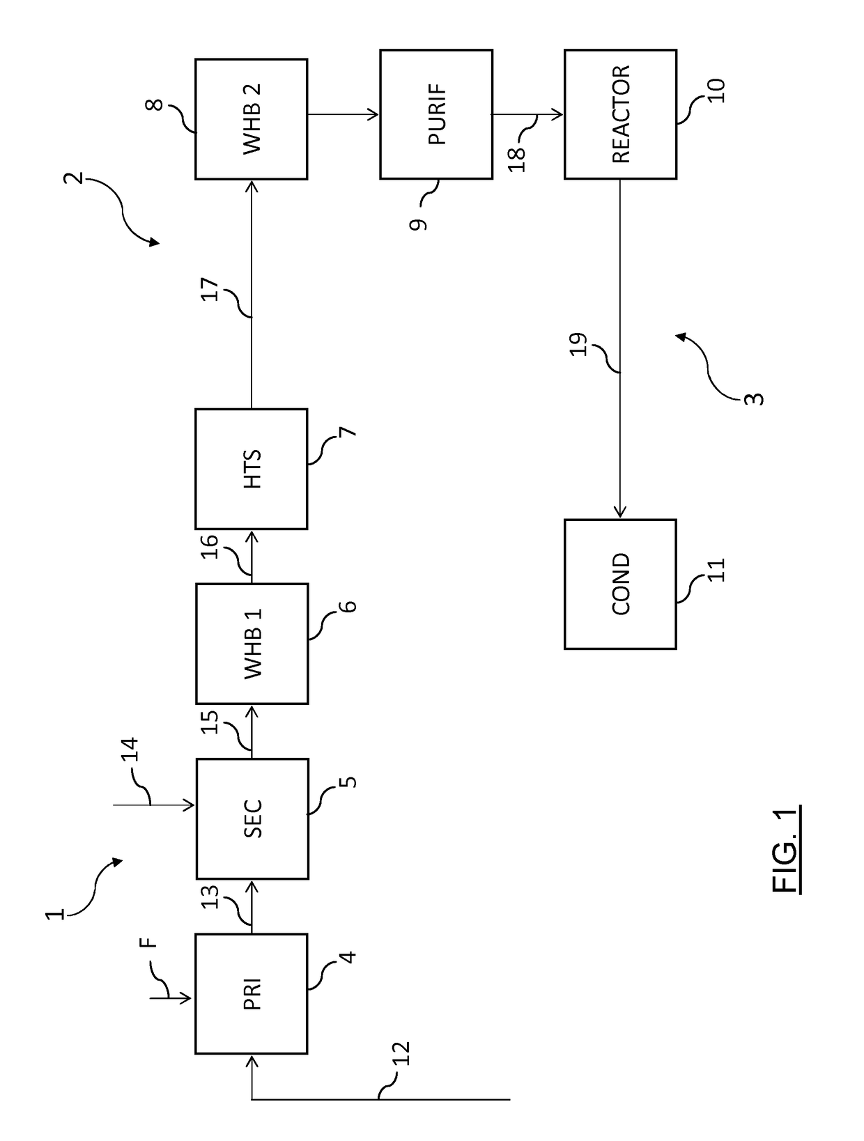
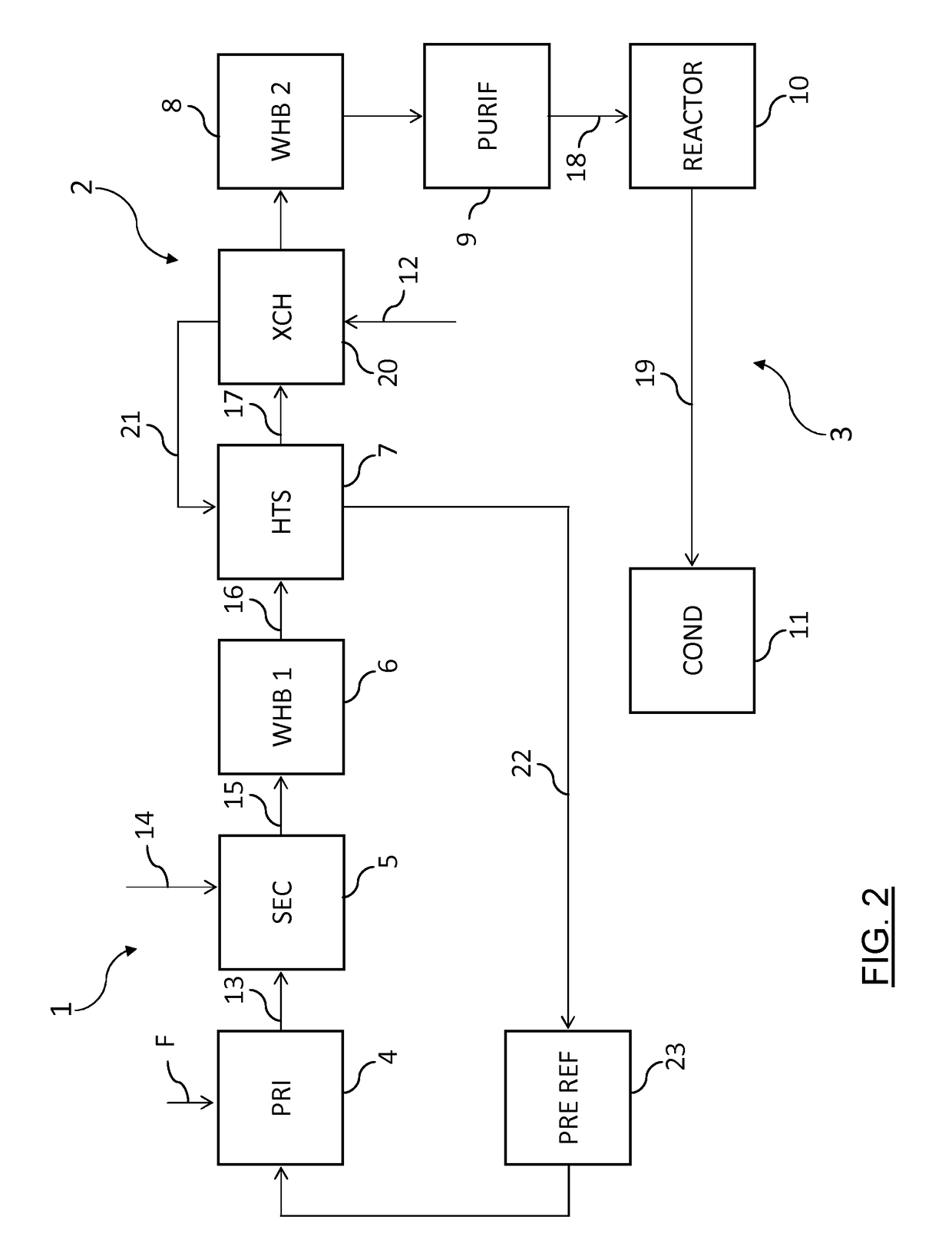
[0052]FIG. 1 illustrates a block scheme of a plant according to the prior art comprising: a front-end including a reforming section 1 and a purification section 2, providing a make-up synthesis gas, and a synthesis loop 3 for the conversion of said synthesis gas into ammonia.

[0053]The reforming section 1 for example comprises a primary reformer 4 and a secondary reformer 5 and a first waste heat boiler 6. The primary reformer 4 is fired by a fuel F, for example natural gas.

[0054]The purification section 2 comprises a high-temperature shift reactor 7, a second waste heat boiler 8 and further equipment denoted by block 9. Said block 9 may include one or more of: low-temperature shift reactor (LTS); remover of carbon dioxide, methanator, hot recovery exchangers (e.g. to preheat water), cryogenic purification etc. according to known technique.

[0055]The synthesis loop 3 comprises a synthesis reactor 10 and further equipment for processing the effluent of the loop, for example an ammonia ...


PUM

PropertyMeasurementUnit
peak temperatureaaaaaaaaaa
temperatureaaaaaaaaaa
gas peak temperatureaaaaaaaaaa

Abstract

Process for the synthesis of ammonia comprising the steps of reforming of a hydrocarbon feedstock into a raw product gas, purification of said raw product gas obtaining a make-up synthesis gas, conversion of said synthesis gas into ammonia; said purification includes shift conversion of carbon monoxide into carbon dioxide and the reforming process requires a heat input which is at least partially recovered from at least one of said step of shift conversion, which is carried out with a peak temperature of at least 450° C., and said step of conversion into ammonia.

Description

FIELD OF APPLICATION[0001]The invention relates to a process for producing ammonia from a hydrocarbon-containing feedstock, a related plant and a method of revamping of related plants.PRIOR ART[0002]The synthesis of ammonia involves the reforming of a hydrocarbon-containing feedstock (usually natural gas) into a synthesis gas in a front-end section and the conversion of said synthesis gas into ammonia in a synthesis loop. A process for producing ammonia synthesis gas is described for example in EP 2 065 337.[0003]The reforming of the hydrocarbon-containing feedstock needs a heat input which is provided at least partially by combustion of a suitable fuel, for example by combustion of a portion of input natural gas. For example a common reforming setup comprises a step of primary reforming with steam and a subsequent step of secondary reforming with an oxidant. The secondary reforming can be carried out in an internally fired reformer (autothermal reformer ATR) without the combustion ...

Claims


Application Information

Patent Timeline
Patent Type & Authority Applications(United States)
IPC IPC(8): C01C1/04C01B3/02C01B3/48
CPCC01C1/0452C01C1/0417C01B3/025C01B3/48C01B2203/1235C01B2203/0283C01B2203/142C01B2203/0244C01B2203/0838C01B2203/0233C01B3/382C01B2203/1241C01B2203/0445C01B2203/068C01B2203/0883C01B2203/025C01B2203/0288Y02P20/129C01B3/02C01B3/32C01C1/04Y02P20/52
Inventor OSTUNI, RAFFAELEFILIPPI, ERMANNOROSSI, UMBERTO
Owner CASALE SA
Learn More