
Underwater Safety Device

a safety device and underwater technology, applied in underwater equipment, special-purpose vessels, instruments, etc., can solve the problems of diver oxygen poisoning, diver's judgment, coordination, and ability to focus mentally, and diver's ability to be able to respond quickly

Active Publication Date: 2018-01-04
HULBERT CHRISTOPHER B
View PDF2 Cites 13 Cited by
  • Summary
  • Abstract
  • Description
  • Claims
  • Application Information

AI Technical Summary

Benefits of technology

The patent describes the use of a buoy attached to a diver. This buoy can be used to rescue the diver in crisis and allow for data transmission so that the diver can communicate with others on the surface.

Problems solved by technology

It can impair a diver's judgment, coordination, and ability to focus mentally.
If, through inattention or the effects of nitrogen narcosis, a diver breathing air descends too deeply in the water, the diver can suffer from oxygen poisoning (as a result of breathing oxygen at too high a partial pressure).
If the diver's computerized valve assembly malfunctions (e.g., sea water seeps into the computer housing and degrades the performance of the valve controller), the diver must be able promptly to adjust the tank valves manually, a sometimes difficult task.
Carbon monoxide is colorless, tasteless, odorless, and toxic.
If a diver ascends too quickly, however, there can be a build-up of nitrogen bubbles in the diver's body, adversely affecting the diver.
A diver who is injured or otherwise under stress may encounter difficulty in ascending at a proper rate or following a desirable dive profile (including safety stops).
Of course, a diver may, at any time, experience an adverse health issue, such as a stroke or heart attack, requiring prompt medical attention.
A muscle cramp (such as a debilitating stomach cramp) can pose a risk to a diver.

Method used


Image

  • Underwater Safety Device
  • Underwater Safety Device
  • Underwater Safety Device

Examples


Embodiment Construction

Generally

[0047]The following detailed description describes various aspects, implementations, and operations of the disclosed system with reference to the accompanying figures. The illustrative aspects, implementations, and operations described herein are not meant to be limiting. It is contemplated that certain aspects of the disclosed system can be arranged and combined in a wide variety of different configurations.

[0048]Unless context suggests otherwise, the features illustrated in each of the figures may be used in combination with one another. Thus, the features should be generally viewed as component aspects of one or more overall implementations, with the understanding that not all illustrated features are necessary for each implementation.

[0049]Any enumeration of elements, blocks, or steps in this disclosure or in any associated claim is for purposes of clarity. Thus, such enumeration should not be interpreted to require or imply that these elements, blocks, or steps adhere ...


PUM


Abstract

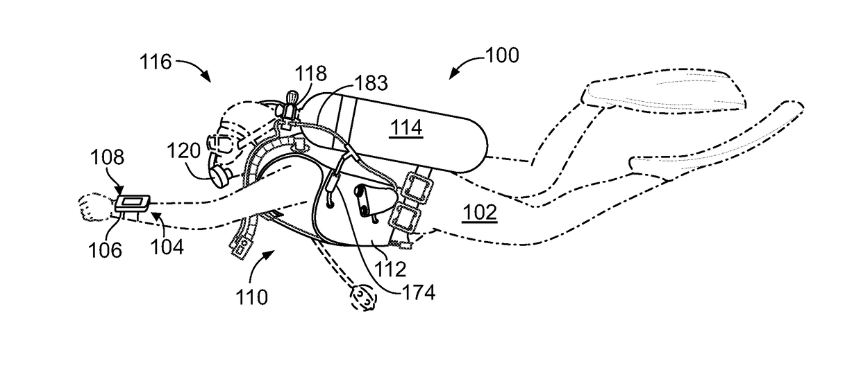
An example safety system for underwater diving includes a biological sensor for detecting a diver in distress, an alarm system, and a rescue deployment system. The sensor detects an anomalous condition and issues an alarm, such as, for example, a buzzer or a flashing light. In another example embodiment, upon determining the existence of a major, persistent, time-critical anomaly, or upon being instructed by the diver, the system inflates the diver's buoyancy compensation device and brings her toward the surface at a controlled rate. In another example embodiment, upon determining the existence of such an anomaly, or upon being instructed by the diver, the system releases a buoy, allowing the buoy to float to the water surface and alert others. In another example embodiment, the buoy detects its position upon reaching the surface and issues a radio signal, indicating distress and its current position.

Description

CLAIM FOR PRIORITY TO RELATED APPLICATION[0001]This application claims priority to U.S. Provisional Application No. 62 / 458,229, which was filed on Feb. 13, 2017 and entitled “Underwater Safety Device.”BACKGROUND[0002]Technical Field: The present system relates to the field of underwater diving and, more particularly, to safety devices used while diving.[0003]Background Art: Underwater diving typically involves a diver breathing from a source of compressed gas. A typical scuba tank for a recreational driver holds gas (e.g., air) at a relatively high pressure (such as 3,000 pounds per square-inch (psi)). The tank is often held by a buoyancy control device (BCD), also referred to as a buoyancy compensator or stabilizer. During use, the BCD is strapped onto the back of a scuba diver.[0004]In a typical single-hose, open-circuit, two-stage scuba system, a first regulator stage reduces the gas pressure in the tank to a low pressure of, for example, 120 to 150 psi. A hose typically supplies...

Claims


Application Information

Patent Timeline
Patent Type & Authority Applications(United States)
IPC IPC(8): B63C11/26B63B22/18A61B5/08B63B22/06A61B5/145B63C11/22A61B5/024
CPCB63C11/26B63C11/2245B63C11/2236B63B22/06B63B2730/00A61B5/02438A61B5/08A61B5/14542B63B22/18A61B5/0205A61B5/02416A61B5/0816A61B5/14551A61B5/742A61B5/746A61B2503/10A61B2560/0242B63C2011/021G08B5/002G08B21/0453G08B21/088G08B25/016G08B21/02
Inventor HULBERT, CHRISTOPHER B.
Owner HULBERT CHRISTOPHER B
Learn More