
Methods for anchoring a heart valve prosthesis in a transcatheter valve implantation procedure

a heart valve and transcatheter valve technology, applied in the direction of surgical staples, nails, medical science, etc., can solve the problems of inability to open the valve properly, inability to recur, stenosis and insufficiency, etc., to prevent further paravalvular leakage, prevent movement of the heart valve prosthesis, and improve the sealing

Active Publication Date: 2018-01-04
MEDTRONIC VASCULAR INC
View PDF1 Cites 5 Cited by
  • Summary
  • Abstract
  • Description
  • Claims
  • Application Information

AI Technical Summary

Benefits of technology

The patent text discusses a method for securing a heart valve replacement in place and preventing leakage or movement after the initial implantation. This is done by using anchor clips that are securely attached to the heart valve and the surrounding tissue to create a better seal and prevent further leakage or failure of the heart valve over time.

Problems solved by technology

Problems that may develop with valves include stenosis, in which a valve does not open properly, and / or insufficiency or regurgitation, in which a valve does not close properly.
Stenosis and insufficiency may occur concomitantly in the same valve.
The effects of valvular dysfunction vary, with regurgitation or backflow typically having relatively severe physiological consequences to the patient.
Taken in combination, these design features can give rise to delivery concerns.
A rapidly expanding frame having one section expanding to a substantially larger diameter than an adjacent section, for instance, can cause the prosthetic heart valve to spring off of the delivery device in a relatively uncontrolled fashion.
This rapid deployment can, in turn, result in the valve body being improperly positioned.
If a delivery system does not have a mechanism to control expansion of such a self-expanding frame, the inflow section of the frame can experience rapid, uncontrolled expansion upon deployment, such that the outflow section may seat improperly within the native mitral valve annulus, and such that the inflow section may fail to anchor sufficiently within the corresponding anatomy of the atrium.
For instance even after a self-expanding valve prosthesis is properly positioned, paravalvular leakage is still a concern as leakage may occur at the time of implantation or may occur after implantation due to changes in the native anatomy, such as elongation of the chordae tendinae, stretching of the native leaflets over time due to the stresses placed thereon by the functioning of a prosthetic mitral valve, and / or the migration of the papillary muscles over time due to the remodeling of the heart that over time.

Method used


Image

  • Methods for anchoring a heart valve prosthesis in a transcatheter valve implantation procedure
  • Methods for anchoring a heart valve prosthesis in a transcatheter valve implantation procedure
  • Methods for anchoring a heart valve prosthesis in a transcatheter valve implantation procedure

Examples


Embodiment Construction

[0025]Specific embodiments of the present invention are now described with reference to the figures, wherein like reference numbers indicate identical or functionally similar elements. The terms “distal” and “proximal” are used in the following description with respect to a position or direction relative to the treating clinician. “Distal” or “distally” are a position distant from or in a direction away from the clinician. “Proximal” and “proximally” are a position near or in a direction toward the clinician. The following detailed description is merely exemplary in nature and is not intended to limit the invention or the application and uses of the invention. Although the description of embodiments hereof are in the context of delivery systems for delivering a prosthetic heart valve within a native mitral valve, the delivery systems of the invention can also be used in other areas of the body, such as for delivering a prosthetic heart valve within a native aortic valve, for deliver...


PUM


Abstract

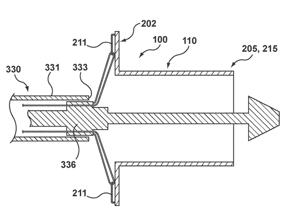
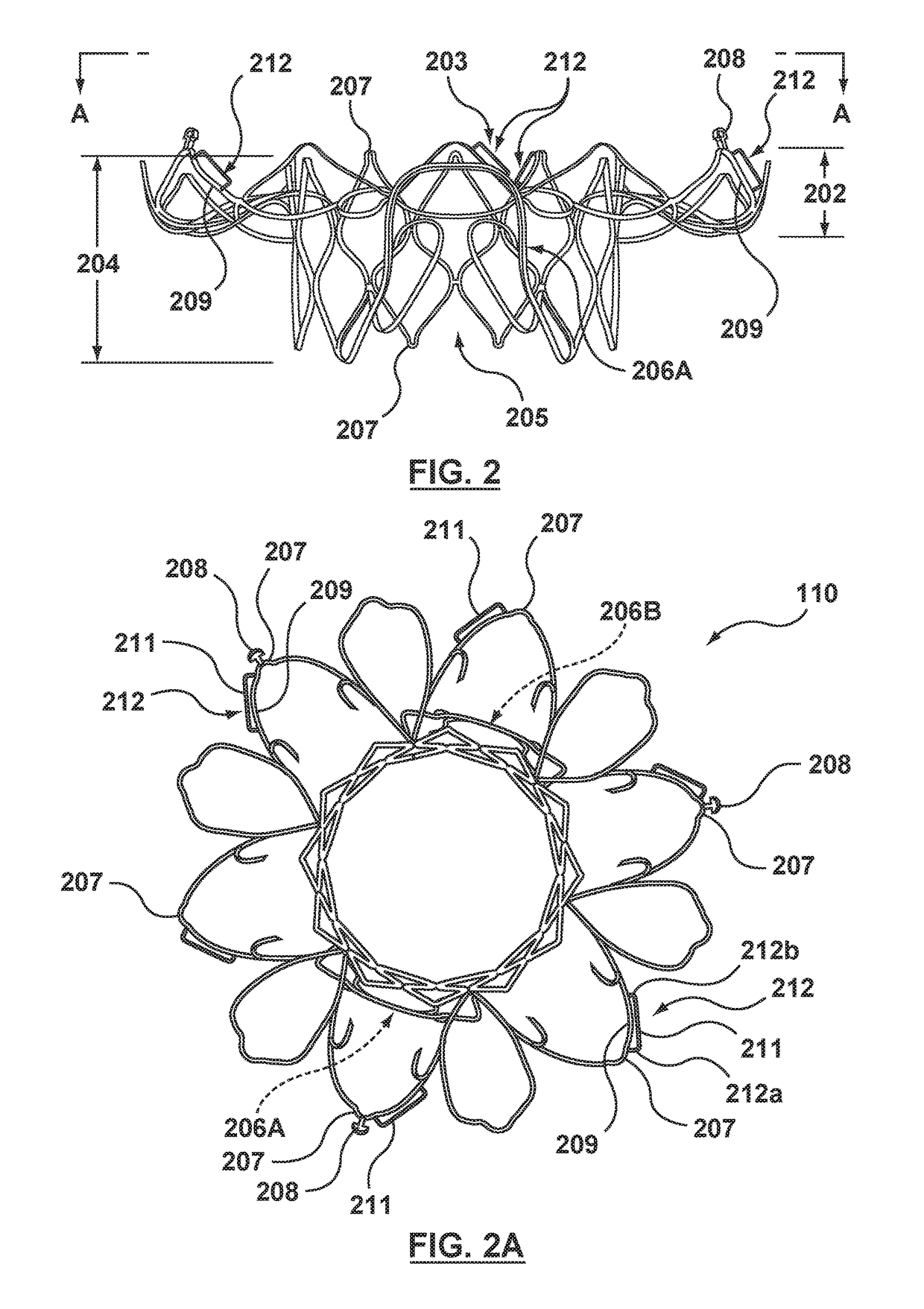
Methods of deploying and securing a heart valve prosthesis are disclosed. A heart valve prosthesis (100) having a plurality of anchor guides (212) is loaded within a catheter-based delivery device, wherein each of the anchor guides is releasably engaged by a respective elongate member (338) and wherein tensioning of the elongate members aids in collapsing the prosthesis during loading. The delivery device is advanced via a transcatheter procedure to position the heart valve prosthesis at an implantation site. The heart valve prosthesis undergoes controlled deployment by controlling the release of tension on the elongate members. After deployment of the heart valve prosthesis, an anchor tool (660) is advanced along a guide member to the anchor guide positioned at a securement site. When the securement site is reached, an anchor clip (662) is released from the anchor tool to secure the prosthesis to the heart.

Description

FIELD OF THE INVENTION[0001]The invention relates to methods for anchoring a heart valve prosthesis deployed within a native heart valve, or previously implanted heart valve prosthesis, in a transcatheter valve implantation procedure.BACKGROUND OF THE INVENTION[0002]A human heart includes four heart valves that determine the pathway of blood flow through the heart: the mitral valve, the tricuspid valve, the aortic valve, and the pulmonary valve. The mitral and tricuspid valves are atrioventricular valves situated between a respective atria and ventricle, while the aortic and pulmonary valves are semilunar valves situated between a respective ventricle and the aorta or pulmonary artery, respectively. Ideally, native leaflets of a heart valve move apart from each other when the valve is in an open position, and meet or “coapt” when the valve is in a closed position. Problems that may develop with valves include stenosis, in which a valve does not open properly, and / or insufficiency or...

Claims


Application Information

Patent Timeline
Patent Type & Authority Applications(United States)
IPC IPC(8): A61F2/24A61B17/068A61B17/064
CPCA61F2/2439A61F2/2418A61B17/0682A61F2/2436A61B17/064A61B2017/0649A61F2220/0016A61F2210/0014A61B17/08A61B2017/22038
Inventor DUFFY, NIALLDWORK, JOSHUA
Owner MEDTRONIC VASCULAR INC
Learn More