
Real-time trace gas sensor using a multi-mode diode laser and multiple line integrated cavity enhanced absorption spectroscopy

a trace gas sensor and integrated cavity technology, applied in the direction of instruments, semiconductor lasers, semiconductor laser arrangements, etc., can solve the problems of reducing sensitivity, and achieve enhanced spectroscopy, high precision measurements, and long effective path length

Inactive Publication Date: 2017-12-14
ADELPHI UNIVERSITY
View PDF14 Cites 10 Cited by
  • Summary
  • Abstract
  • Description
  • Claims
  • Application Information

AI Technical Summary

Benefits of technology

The invention is a highly sensitive trace gas sensor that uses a simplified design and is capable of high precision measurements in real-time. It uses a broadband semiconductor laser with Multiple line integrated absorption spectroscopy (MLIAS) to record and average data much faster than other laser-based cavity enhanced techniques. The laser excites a large number of cavity modes simultaneously, reducing the sensor's susceptibility to vibration. The use of a broadband laser allows for faster data recording and averaging, and simplifies the alignment process. The invention offers the potential for highly sensitive, real-time monitoring of trace gas concentrations.

Problems solved by technology

A key design issue, however is that the cavity mirrors need to be large enough to allow multiple reflections within the cavity without causing beam overlap on the mirrors.
This requirement for using large mirrors (diameter ˜50 mm) causes a complication.
In order to maintain a small volume while using larger mirrors, one must reduce the spacing between the mirrors, resulting in reduced sensitivity due to the shorter path length.

Method used


Image

  • Real-time trace gas sensor using a multi-mode diode laser and multiple line integrated cavity enhanced absorption spectroscopy
  • Real-time trace gas sensor using a multi-mode diode laser and multiple line integrated cavity enhanced absorption spectroscopy
  • Real-time trace gas sensor using a multi-mode diode laser and multiple line integrated cavity enhanced absorption spectroscopy

Examples


Embodiment Construction

[0029]A new trace gas detection technique and its applications are discussed herein. In the following description, for purposes of explanation, numerous specific details are set forth in order to provide a thorough understanding of the present invention. It will be evident, however, to one skilled in the art that the present invention may be practiced without these specific details.

[0030]The present disclosure is to be considered as an exemplification of the invention, and is not intended to limit the invention to the specific embodiment illustrated by the figures or description below. More specifically, some of the details provided below include a demonstration of the invention to detect NO2. The details specific to NO2 detection (for example the use of a multi-mode diode laser emitting near 405 nm), pertain to this demonstration and are not intended to limit the invention to this specific laser, wavelength or molecular species.

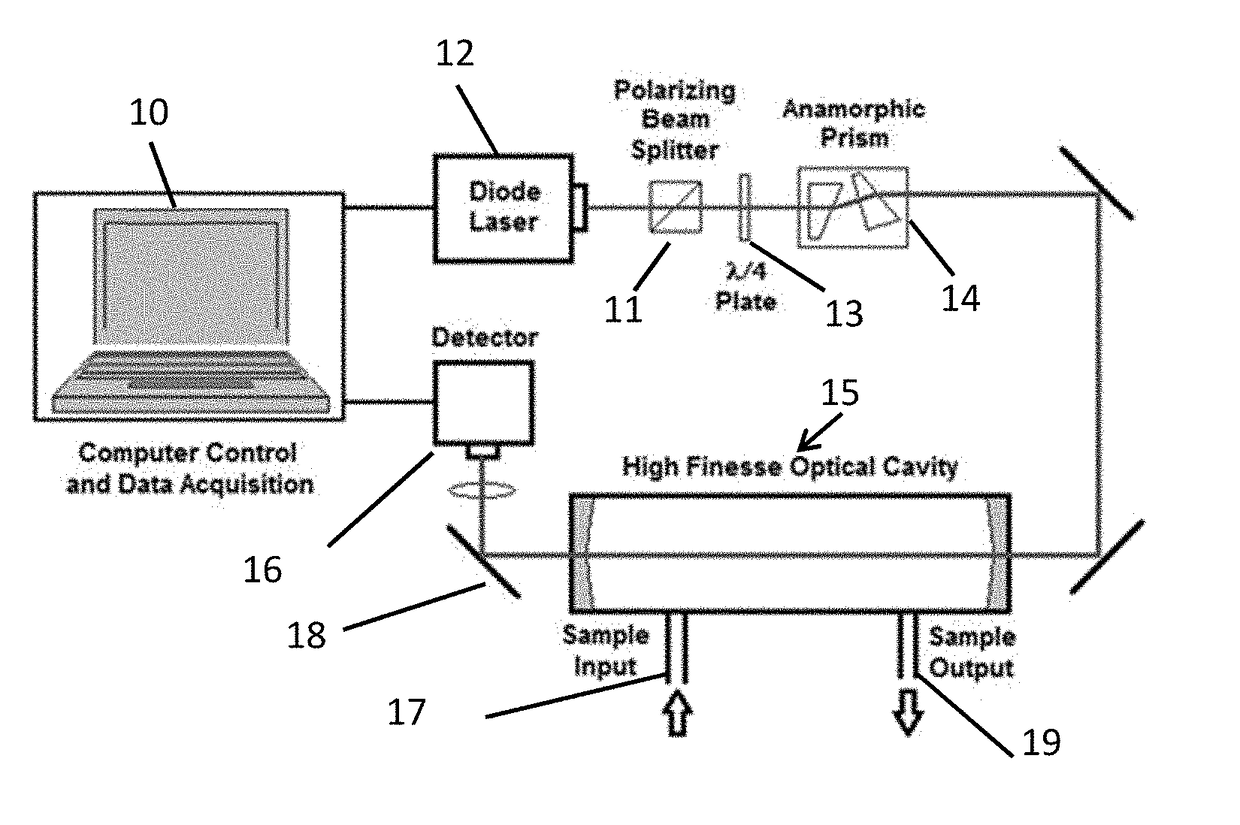
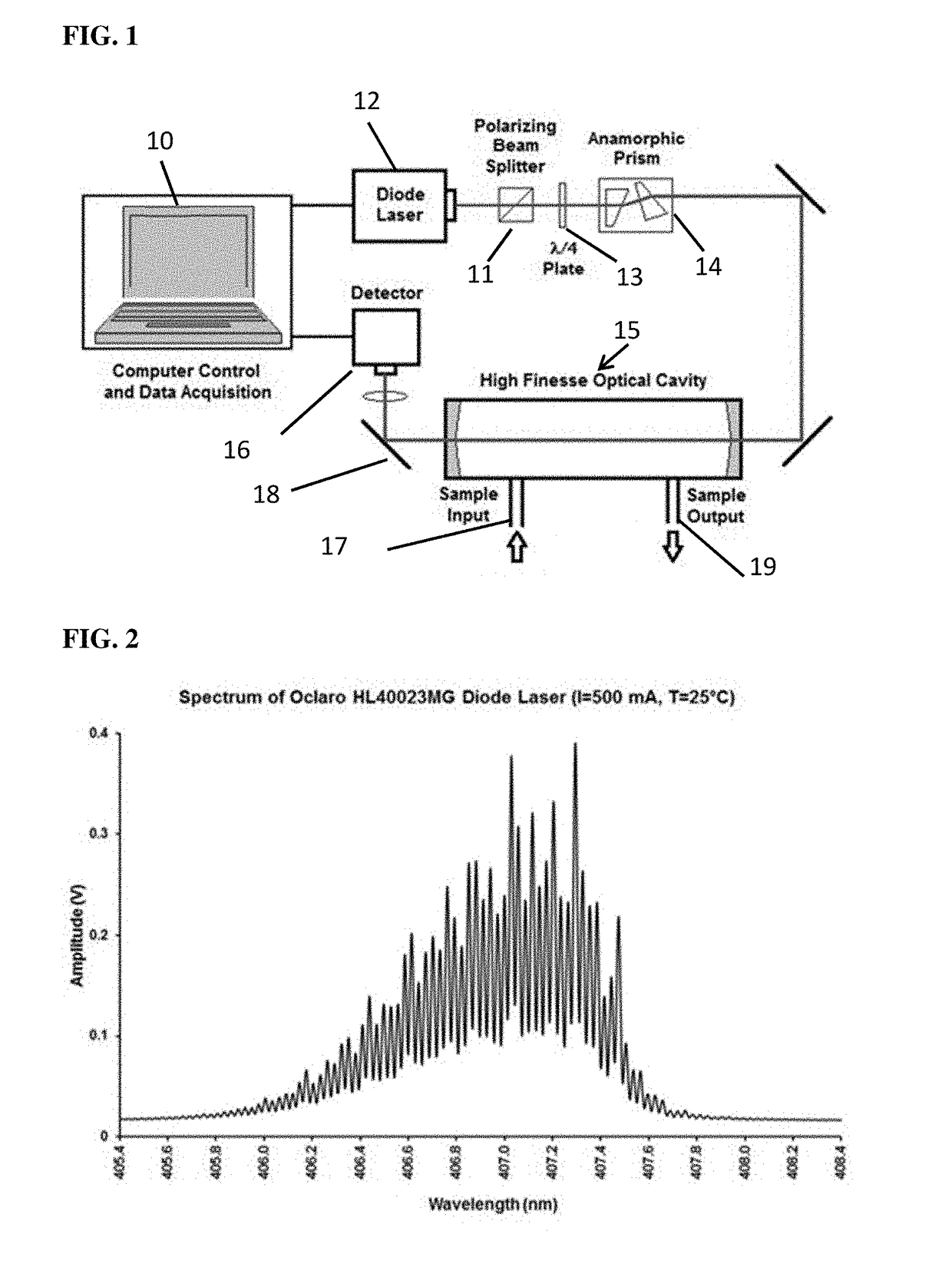
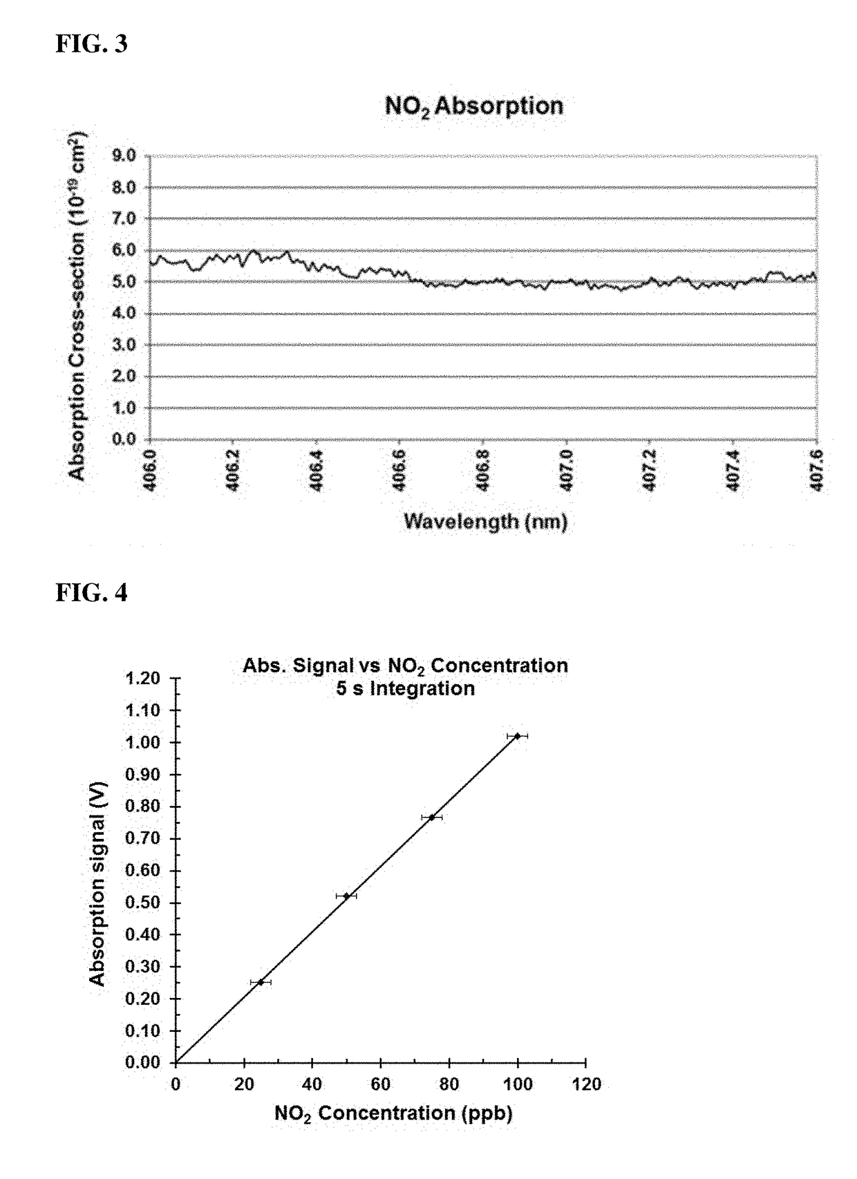
[0031]FIG. 1 shows apparatus as configured for demonst...


PUM

PropertyMeasurementUnit
FWHMaaaaaaaaaa
widthaaaaaaaaaa
cavity enhanced absorption spectroscopyaaaaaaaaaa

Abstract

A highly sensitive trace gas sensor based on a Fabry-Perot semiconductor laser and cavity enhanced absorption spectroscopy is designed to be capable of measuring sub-ppb concentrations of trace gases in real time. The broad frequency range of the multi-mode Fabry-Perot semiconductor laser spans a large number of absorption lines of the species of interest enabling multiple line integrated absorption spectroscopy which improves the sensitivity of detection. Additionally, the broad wavelength range of the laser excites a large number of cavity modes simultaneously, thereby reducing the sensor's susceptibility to vibration and thermal fluctuations making it suitable for field based monitoring applications. Using a high finesse optical cavity also enhances the sensitivity of the sensor by providing large path lengths, on the order of kilometers, in a small volume. Relatively high laser power is used to compensate for the low coupling efficiency of a broad linewidth laser to the optical cavity.

Description

CROSS-REFERENCE TO RELATED APPLICATION[0001]This patent application claims priority to U.S. Provisional Patent Application Ser. No. 62 / 347,972 filed on Jun. 9, 2016, the entire contents of which are incorporated herein by reference in its entirety.FIELD OF THE INVENTION[0002]The present invention relates to highly sensitive trace gas sensors capable of measuring sub-ppb concentrations in real-time. Sensors of this type are useful in the detection of trace gas species in the environment and industrial processes as well as in power plant and automobile emissions. In particular, it may be used to detect pollutants, contaminants and explosive vapors, as well as to indicate the presence of drugs, steroids and molecular biomarkers (of numerous diseases and conditions) in samples of exhaled breath. The invention makes use of a novel, spectroscopic approach which is highly selective to the target gas (i.e., its susceptibility to false readings is minimized), and is capable of recording meas...

Claims


Application Information

Patent Timeline
Patent Type & Authority Applications(United States)
IPC IPC(8): G01N21/17G01N21/31H01S5/40G01N33/497
CPCG01N21/1702G01N33/497G01N2021/1704H01S5/4012G01N21/31G01N21/031G01N21/39G01N2021/3129
Inventor RAO, GOTTIPATYKARPF, ANDREAS
Owner ADELPHI UNIVERSITY
Learn More