
Trajectory Optimization in Radiotherapy Using Sectioning

a sectioning and trajectory optimization technology, applied in the field of trajectory optimization and radiation treatment planning, can solve the problems of affecting the treatment effect, the connection between the ideal region and the incident angle, and the technique was not widely adopted into mainstream clinical use, etc., to achieve the effect of avoiding degradation of trajectory optimization quality, optimal trajectories, and fewer mlc contention issues

Active Publication Date: 2017-12-14
THE BOARD OF TRUSTEES OF THE LELAND STANFORD JUNIOR UNIV
View PDF4 Cites 23 Cited by
  • Summary
  • Abstract
  • Description
  • Claims
  • Application Information

AI Technical Summary

Benefits of technology

This patent introduces a new approach to optimized trajectory in radiotherapy using sectioning. The TORUS approach improves the quality of trajectory optimization and reduces the likelihood of treatment failures. It maps the connectedness of target regions to form optimal trajectories and selects beams based on a combination of dose section and score section to minimize interference and maximize angular spread. The result is a more efficient and effective radiotherapy treatment.

Problems solved by technology

Complex for the time, the technique was not widely adopted into mainstream clinical use, possibly due to the risk associated with accurately administering a highly dynamic treatment without sufficient safety and verification technologies.
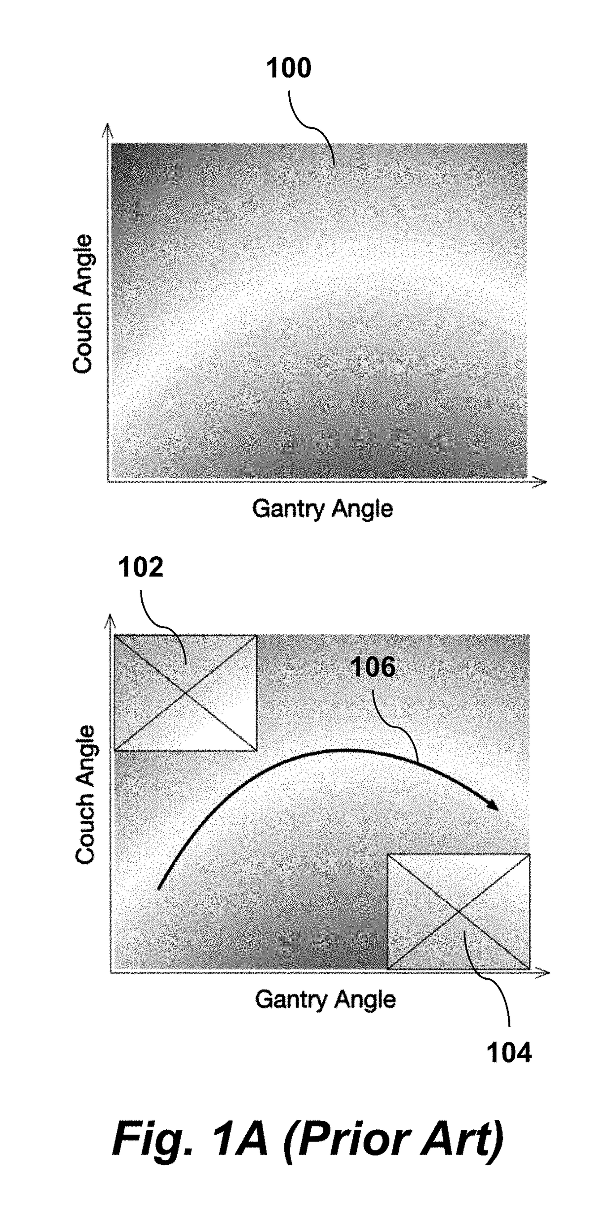
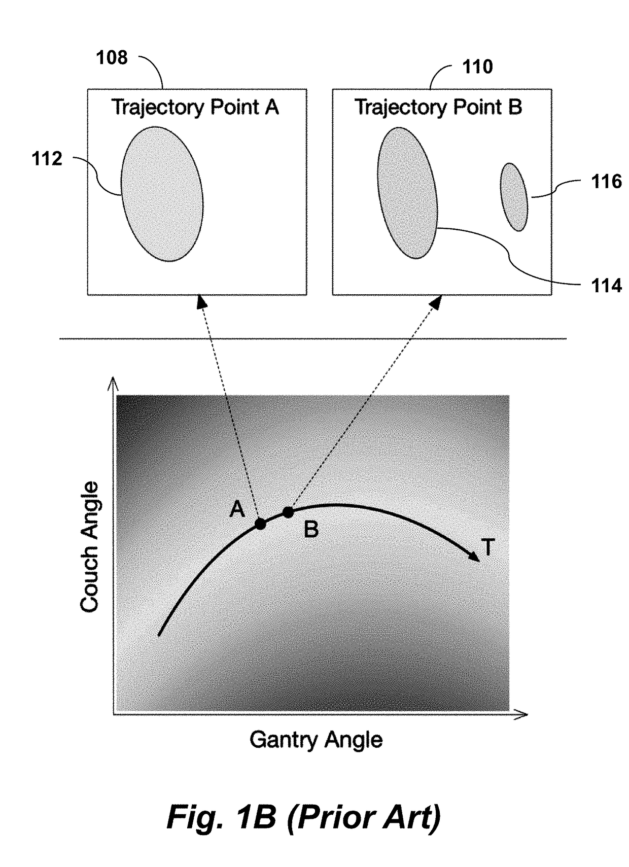
Using this common approach, a fundamental loss of information occurs: The connectedness of ideal regions to treat, from one incident angle to the next, is entirely lost.
By using only a single calculated score for each incident beam angle, the geometrical relationship of adjacent apertures is not preserved and the deliverable trajectories ultimately degrade from inadequate dynamic multi-leaf collimator (MLC) delivery capabilities and MLC aperture forming contention issues.
Consequently, the resulting trajectories cannot be considered optimal using any of the approaches summarized above.
Yet, in this example, such a solution is probabilistically undiscoverable without some mathematical consideration of MLC synchronization.

Method used


Image

  • Trajectory Optimization in Radiotherapy Using Sectioning
  • Trajectory Optimization in Radiotherapy Using Sectioning
  • Trajectory Optimization in Radiotherapy Using Sectioning

Examples


Embodiment Construction

Definitions

[0049]The term “BEV” or “beam's eye view” refers to a perspective on the patient assumed from the direction of the incident radiation.

[0050]The term “MLC” or “multi-leaf collimator” refers to a component of the beam shaping elements of the radiation delivery device.

[0051]The term “monitor unit” or “MU” refers to a measurable unit of charge collected by the radiation delivery device and relates to the amount of radiation exiting the radiation delivery device.

[0052]The term “volumetric modulated arc therapy” or “VMAT” refers to a technique of irradiating a patient with a delivery device that forms an arc-like trajectory about the patient using a rotating mechanical gantry system.

Overview

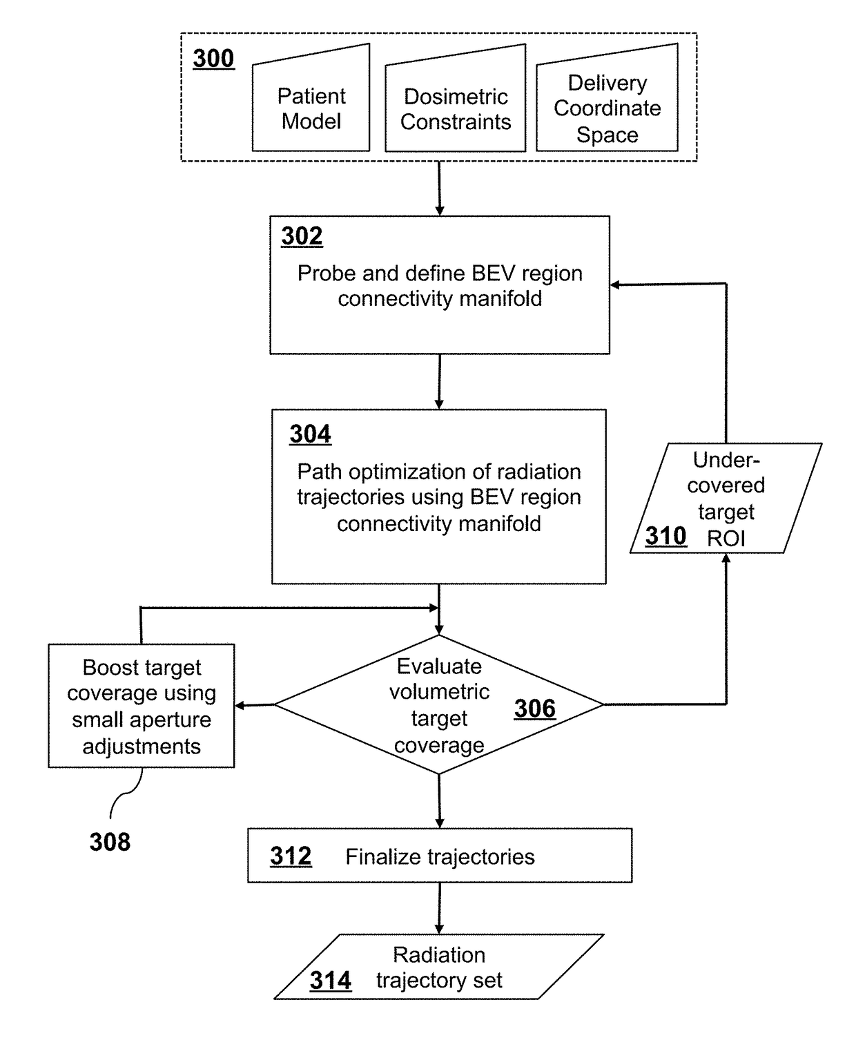
[0053]FIG. 3 describes the process of generating trajectories with TORUS. The inputs to the algorithm are shown in row 300: The patient's model (ROI—regions of interest), dosimetric constraints, and the delivery coordinate space corresponding to the delivery device and patient configuration....


PUM


Abstract

A radiation therapy treatment method includes providing a patient model, dosimetric constraints, delivery motion constraints, and delivery coordinate space of a radiation delivery device, where the delivery coordinate space is represented as a mesh with vertices connected by edges, where the vertices correspond to directions of a beam eye view (BEV) of the radiation delivery device, where each BEV has corresponding area elements resulting from beam collimation. BEV region connectivity manifolds are constructed from the patient model, the dosimetric constraints, the delivery coordinate space, and existing beam trajectories, wherein each of the BEV region connectivity manifolds represents connections between contiguous 2D target regions, where each of the 2D target regions is defined at each of the vertices of the delivery coordinate space. Beam trajectories are selected based on region connectedness information in the BEV region connectivity manifolds, the dosimetric constraints, the delivery motion constraints, and the existing beam trajectories. Radiation is delivered using the radiation delivery device in accordance with the beam trajectories.

Description

CROSS-REFERENCE TO RELATED APPLICATIONS[0001]This application claims priority from U.S. Provisional Patent Application 62 / 349,420 filed Jun. 13, 2016, which is incorporated herein by reference. This application claims priority from U.S. Provisional Patent Application 62 / 422,731 filed Nov. 16, 2016, which is incorporated herein by reference.STATEMENT REGARDING FEDERALLY SPONSORED RESEARCH OR DEVELOPMENT[0002]None.FIELD OF THE INVENTION[0003]The present invention relates generally to radiotherapy and radiation treatment planning. More specifically, it relates to improved techniques for determining radiation beam trajectories.BACKGROUND OF THE INVENTION[0004]In recent years, radiotherapy has experienced a profound reduction in delivery times and improvement in plan quality with the establishment of dynamic gantry treatments such as Volumetric Modulated Arc Therapy (VMAT) [Otto, 2008, Yu, 1995]. The success of VMAT has no doubt motivated a substantial wave of research in furthering dyna...

Claims


Application Information

Patent Timeline
Patent Type & Authority Applications(United States)
IPC IPC(8): A61N5/10
CPCA61N5/1081A61N5/103A61N5/1047
Inventor BUSH, KARLHADSELL, MICHAELLOCKE, CHRISTOPHERXING, LEI
Owner THE BOARD OF TRUSTEES OF THE LELAND STANFORD JUNIOR UNIV
Learn More