
Unmanned aerial vehicle with deployable transmit/receive module apparatus with ramjet

a transmit/receive module and unmanned aerial vehicle technology, applied in wave based measurement systems, machines/engines, process and machine control, etc., can solve the problems of significant detection range of tactical combat aircraft entering contested or hostile airspace, significant complexity of aircraft reconnaissance and interdiction, etc., and achieve the effect of reducing speed

Active Publication Date: 2017-11-30
THE BOEING CO
View PDF0 Cites 18 Cited by
  • Summary
  • Abstract
  • Description
  • Claims
  • Application Information

AI Technical Summary

Benefits of technology

The patent describes a system for detecting targets using bistatic radar. The system involves a UAV that has a ramjet engine for supersonic cruise and a set of deployable antenna arms. These arms can be extended to act as air brakes and align the radar receiver with a target. The UAV is navigated by a mothership aircraft that has its own radar system. The system detects reflected radar pulses and transmits the data to the mothership aircraft through a communications link. The technical effect of this system is improved target detection and more accurate tracking of moving targets.

Problems solved by technology

Aircraft reconnaissance and interdiction has been significantly complicated by the appearance of highly accurate and often minimally detectable antiaircraft systems.
Consequently, most current tactical combat aircraft entering into contested or hostile airspace are placed at risk.
The detection range of these systems may be significant thus requiring a significant standoff distance to avoid the contested airspace, often beyond the effective range of radar systems employed in current tactical aircraft.
The use of stealth aircraft to penetrate hostile airspace and accomplish such missions provides a certain level of increased survivability but such aircraft are highly expensive assets and are used only upon critical need.
However, speed of typical UAV system requires significant standoff time for aircraft acting as a mothership for deployment.

Method used


Image

  • Unmanned aerial vehicle with deployable transmit/receive module apparatus with ramjet
  • Unmanned aerial vehicle with deployable transmit/receive module apparatus with ramjet
  • Unmanned aerial vehicle with deployable transmit/receive module apparatus with ramjet

Examples


Embodiment Construction

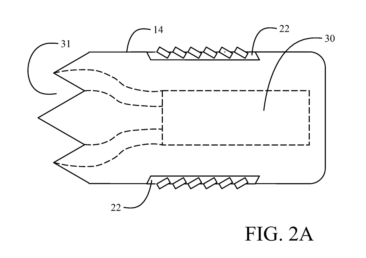
[0013]Current bistatic radar systems employing UAVs provide nose mounted or side mounted antenna with conventional propulsion. This reduces bi-static sensor performance as well as the overall speed of the UAV. The system and methods described herein provide embodiments which solves these problems by employing a ramjet in a UAV with deployable side mounted antennas. The ramjet greatly increases the instantaneous acceleration and top speed of the UAV for ingress into and egress from the target area. The front section of the UAV is replaced with a ramjet inlet, instead of the sensor suites. The Transmit / Receive modules (T / R Modules) of the Active Electronically Scanned Array (AESA) antenna are mounted on the sides of the UAV in multiple panels. These T / R modules are installed with forward tilted positions so that when the panels deploy the planar face of the T / R modules all face forward directly towards the direction of motion, reducing the need for beam steering and thus increasing th...


PUM


Abstract

A system for bistatic radar target detection employs an unmanned aerial vehicle (UAV) having a ramjet providing supersonic cruise of the UAV. Deployable antenna arms support a passive radar receiver for bistatic reception of reflected radar pulses. The UAV operates with a UAV flight profile in airspace beyond a radar range limit. The deployable antenna arms have a first retracted position for supersonic cruise and are adapted for deployment to a second extended position acting as an airbrake and providing boresight alignment of the radar receiver. A mothership aircraft has a radar transmitter for transmitting radar pulses and operates with an aircraft flight profile outside the radar range limit. A communications data link operably interconnects the UAV and the tactical mothership aircraft, transmitting data produced by the bistatic reception of reflected radar pulses in the UAV radar antenna to the mothership aircraft.

Description

BACKGROUND INFORMATIONField[0001]Embodiments of the disclosure relate generally to bistatic tactical radar applications employing supersonic unmanned aerial vehicles and more particularly to a system employing small unmanned air vehicles (UAV) having transmit / receive antennae deployable from a retracted supersonic cruise position to an extended triangular form.Background[0002]Aircraft reconnaissance and interdiction has been significantly complicated by the appearance of highly accurate and often minimally detectable antiaircraft systems. Consequently, most current tactical combat aircraft entering into contested or hostile airspace are placed at risk. The detection range of these systems may be significant thus requiring a significant standoff distance to avoid the contested airspace, often beyond the effective range of radar systems employed in current tactical aircraft. The use of stealth aircraft to penetrate hostile airspace and accomplish such missions provides a certain level...

Claims


Application Information

Patent Timeline
IPC IPC(8): G01S7/02G01S7/00B64C39/02F02K7/10B64D5/00G05D1/00B64C30/00
CPCG01S7/021G01S7/003B64C39/024B64C30/00F05D2220/10G05D1/0088G05D1/0011F02K7/10B64D5/00B64C1/36G01S7/03H01Q1/084H04B7/18506B64U50/15B64U2201/10B64U2201/20B64U2101/20B64U70/20F42B10/48G01S13/003G01S13/87H01Q1/287B64C9/326B64D7/00B64D47/02B64D27/20H01Q1/28B64C3/38
Inventor KIM, INYOUNG DANIELWILSON, RYAN S.
Owner THE BOEING CO
Learn More