
Back frame structure for vehicle seat

a back frame and vehicle seat technology, applied in vehicle components, vehicle safety belts, transportation and packaging, etc., can solve the problems of inability to increase the bending rigidity in front-rear direction, the shape of the outline shape of the high-strength side frame and/or the cross section of the normal-strength side frame is difficult to reduce the thickness of a constituent component, and the effect of increasing the bending rigidity

Active Publication Date: 2017-11-30
TOYOTA BOSHOKU KK
View PDF32 Cites 3 Cited by
  • Summary
  • Abstract
  • Description
  • Claims
  • Application Information

AI Technical Summary

Benefits of technology

The patent text is about a structure for a vehicle seat that increases the bending rigidity of the side frames in the front-rear and right-left directions. The structure includes a lower frame that connects the lower end sides of the side frames to restrain the inclination of the back frame. However, the lower frame does not increase bending rigidity in the front-rear direction and bending rigidity in the right-left direction, making it difficult to reduce the size and thickness of the structure. The technical effect of the patent is to provide a structure that can increase the bending rigidity of the side frames to address these limitations.

Problems solved by technology

However, the lower pipe does not have a function to increase bending rigidity in a front-rear direction and bending rigidity in the right-left direction in terms of the high-strength side frame and / or the normal-strength side frame.
This makes it difficult to reduce the size of an outline shape of a cross section of the high-strength side frame and / or a cross section of the normal-strength side frame.
This also makes it difficult to reduce a thickness of a constituent component so as to reduce the weight.

Method used


Image

  • Back frame structure for vehicle seat
  • Back frame structure for vehicle seat
  • Back frame structure for vehicle seat

Examples


Embodiment Construction

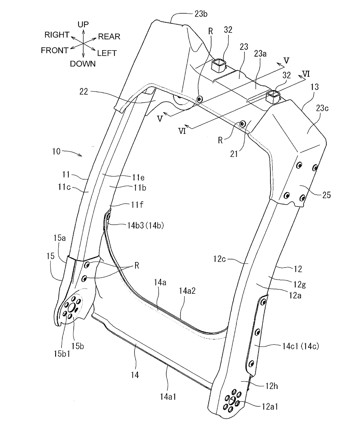
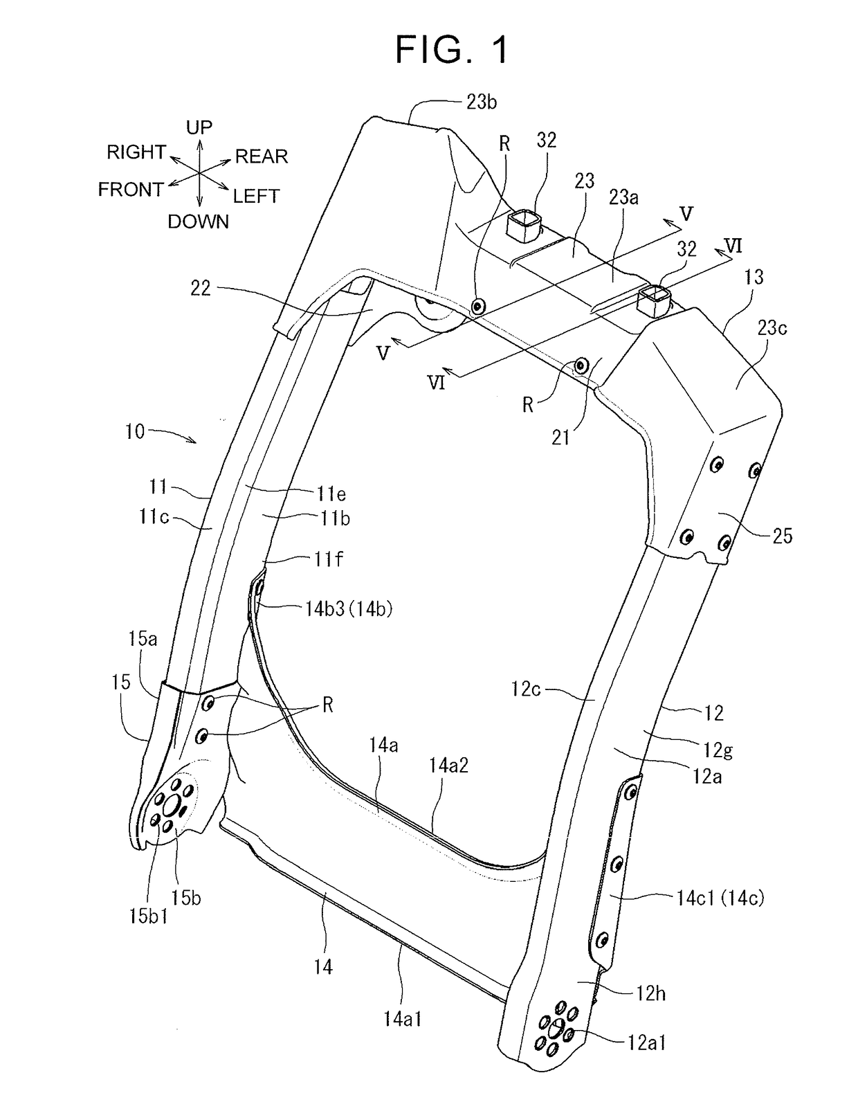
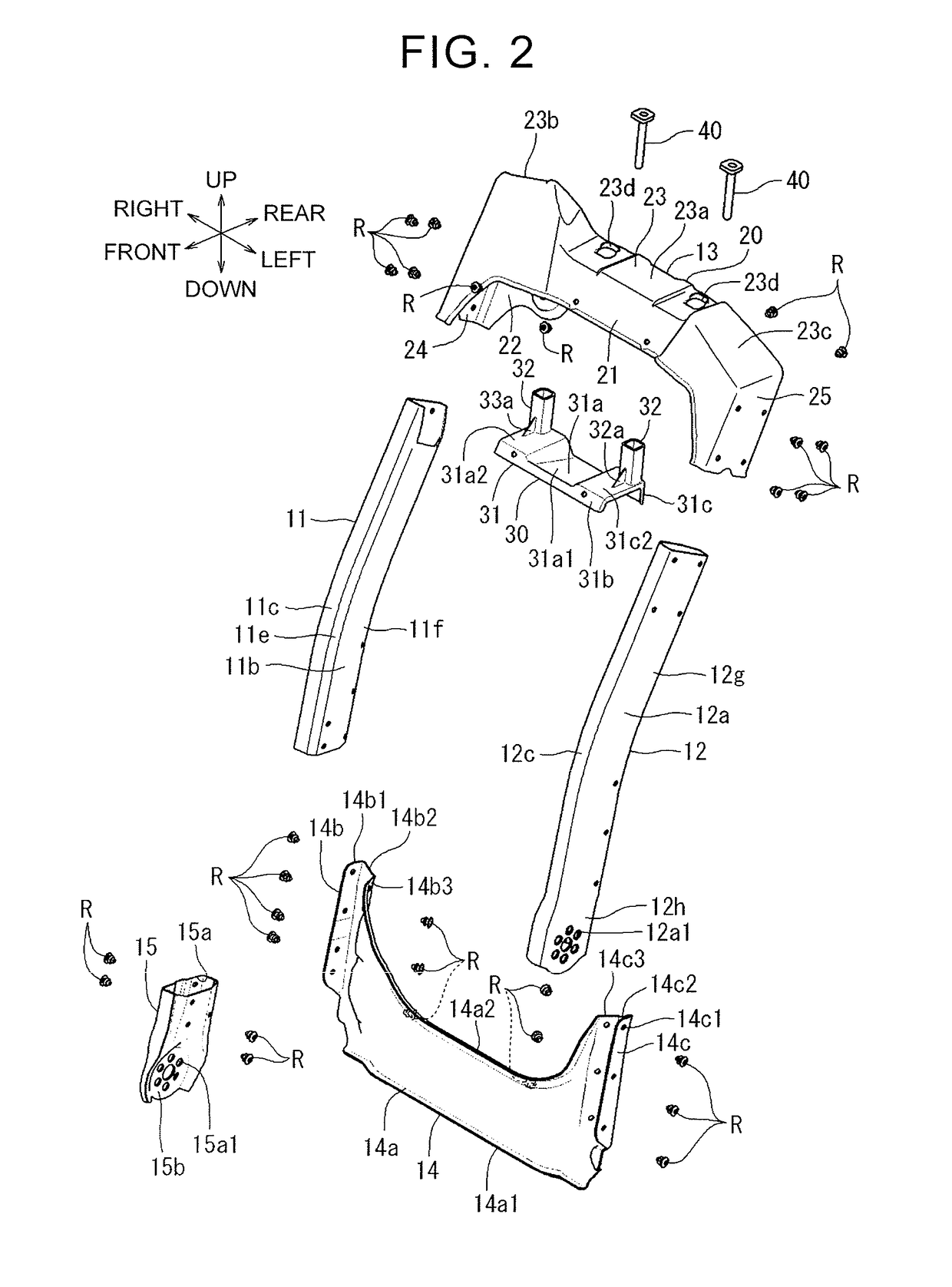
[0030]FIG. 1 to FIG. 13 illustrate one embodiment of the disclosure. The present embodiment is an example in which the disclosure is applied to a back frame (hereinafter just referred to as the back frame) for an automobile seat. In the drawings, respective arrows indicate respective directions of an automobile and an automobile seat at the time when the automobile seat is attached to a floor of the automobile. The back frame is attached to the automobile seat. In the following description, a description about a direction shall be performed on the basis of these directions.

[0031]As illustrated in FIG. 1 to FIG. 3, a back frame 10 of the present embodiment is a back frame for a right automobile seat with a built-in seat belt, and a webbing winding apparatus (not shown) of a seat belt system can be attached thereto. The back frame 10 includes a right side frame 11 extending in an up-down direction, a left side frame 12 extending in the up-down direction, an upper frame 13 connecting r...


PUM


Abstract

A back frame structure for a vehicle seat includes: a pair of right and left side frames extending in an up-down direction; and a lower frame configured to connect a lower end side of the right side frame and a lower end side of the left side frame, wherein: at least one side frame out of the pair of right and left side frames is fitted to one connection portion, which is a connection portion of the lower frame with respect to the one side frame, so as to form one fitting portion; and the one fitting portion is configured such that a geometrical-moment of inertia along an axis extending to a predetermined first direction gradually increases from an upper part of the one fitting portion to a lower part of the one fitting portion.

Description

INCORPORATION BY REFERENCE[0001]The disclosure of Japanese Patent Application No. 2016-104019 filed on May 25, 2016 including the specification, drawings and abstract is incorporated herein by reference in its entirety.BACKGROUND1. Technical Field[0002]The disclosure relates to a back frame structure for a vehicle seat to be provided in vehicles such as an automobile, an airplane, a ship, and a train.2. Description of Related Art[0003]As one of back frame structures for a vehicle seat, there is such a back frame structure in which a gate-shaped back frame having a generally reverse U-shape in a front view and serving as a framework of a seatback is formed such that upper end sides of a pair of side frames extending in an up-down direction are connected by an upper frame in a bridged manner. A back frame of this type as described in Japanese Patent Application Publication No. 2014-156212 (JP 2014-156212 A) is a back frame for a vehicle seat with a built-in three point seat belt. In t...

Claims


Application Information

Patent Timeline
IPC IPC(8): B60N2/68B60R22/18B60R22/26
CPCB60N2/68B60R22/26B60R2022/1818B60R22/18
Inventor MIZOBATA, HIROSHIAKAIKE, FUMITOSHI
Owner TOYOTA BOSHOKU KK
Learn More