
Stereoscopic display

a display and stereoscopic technology, applied in the field of interactive three-dimensional displays, can solve the problems of accommodation-vergence conflict, heavy and awkward use, and the limitation of hmds to displaying content at a single fixed or finite set of focal lengths

Inactive Publication Date: 2017-11-16
SPATIAL INTELLIGENCE LLC
View PDF1 Cites 18 Cited by
  • Summary
  • Abstract
  • Description
  • Claims
  • Application Information

AI Technical Summary

Benefits of technology

The patent describes a display system that can create a virtual environment that appears to originate from a target viewing volume. The system includes a beam combiner that combines two images from different displays, a mirror that reflects the combined images towards the viewer, and a processor that adjusts the display and mirror positions to align the image with the target viewing volume. The system also includes tracking sensors to detect the position and orientation of objects in relation to the display, and a processor that updates the virtual environment based on the detected information. The technical effect of this system is that it creates a more immersive virtual environment that aligns with the viewer's perspective.

Problems solved by technology

Head-mounted stereoscopic displays (“HMD”) were proposed in some efforts as a solution, but these are heavy and awkward to use because the cables running to the HMD can restrict the freedom of movement of the user.
HMDs are limited to displaying content at a single fixed or finite set of focal lengths.
This disparity may result in accommodation-vergence conflict where the eyes converge on a plane at a certain distance but are accommodated at a plane at another distance.
Breaking of the natural accommodation-vergence relationship can lead to eye fatigue and result in difficulty achieving optical fusion where left and right images no longer appear fused.
However, as the nature of surgery requires surgeons to arbitrarily move closer to patients for more detail and further away to establish the overall layout, there would be frequent significant disparities in the regions between the focal lengths.
Head-mounted displays are also especially prone to temporal misalignment in the imagery as a result of latency.
In medical settings, the distance between the surgeon and patient can be enough to introduce significant latency issues.
Another issue with using head-mounted displays in surgical settings is that assistants are not able to observe with the surgeon the augmented graphics presented in context with the patient unless they themselves are wearing head-mounted displays, which adds additional cost and complexity to the system.
Assistants are usually left to follow along on standard overhead displays, with the original disadvantage of not being able to fuse the patient data with actual anatomy.
For example, such display systems may result in the viewer repeatedly shifting focus between the projected image plane and the subject, which is unintuitive and could lead to, for example, blurred vision and / or inaccurate movements during surgery.
Other shortcomings of such display systems may include large system footprints, reduced access to patients, weak and expensive equipment, latency in viewer movement tracking, and inducement of eye strain, fatigue, and dizziness in the viewer.

Method used


Image

  • Stereoscopic display
  • Stereoscopic display
  • Stereoscopic display

Examples


Embodiment Construction

[0037]In the following description, reference is made to exemplary embodiments in which the disclosure may be practiced. These embodiments are described in sufficient detail to enable those skilled in the art to practice the concepts disclosed herein, and it is to be understood that modifications to the various disclosed embodiments may be made, and other embodiments may be utilized, without departing from the spirit and scope of the present disclosure. The following detailed description is, therefore, not to be taken in a limiting sense.

[0038]Reference throughout this specification to “one embodiment,”“an embodiment,”“one example,” or “an example” means that a particular feature, structure, or characteristic described in connection with the embodiment or example is included in at least one embodiment of the present disclosure. Thus, appearances of the phrases “in one embodiment,”“in an embodiment,”“one example,” or “an example” in various places throughout this specification are no...


PUM


Abstract

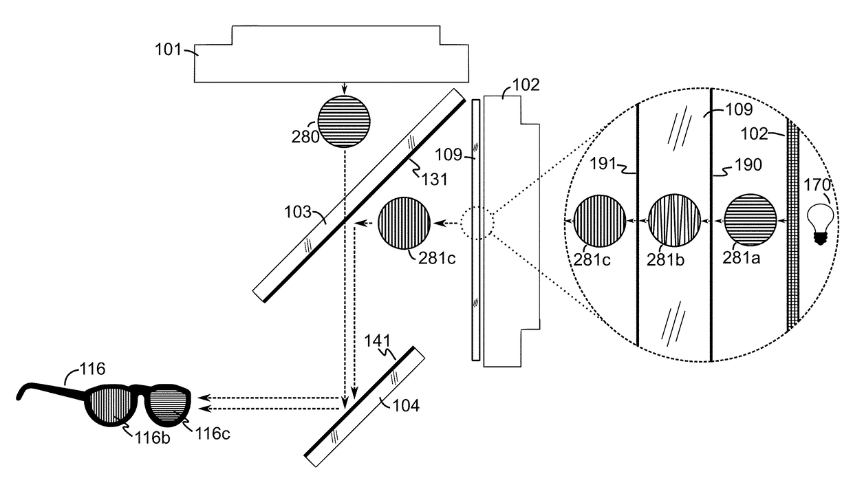
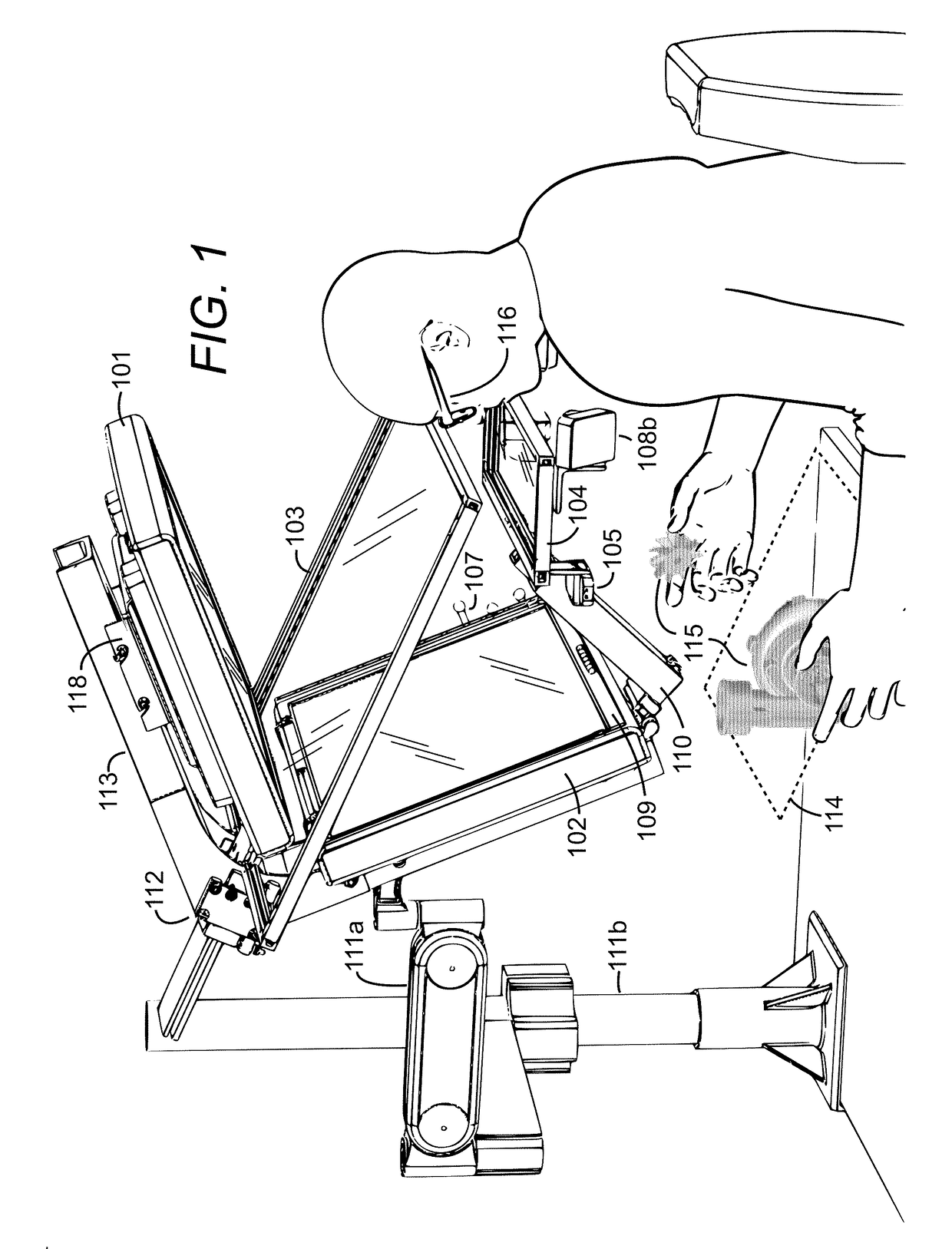
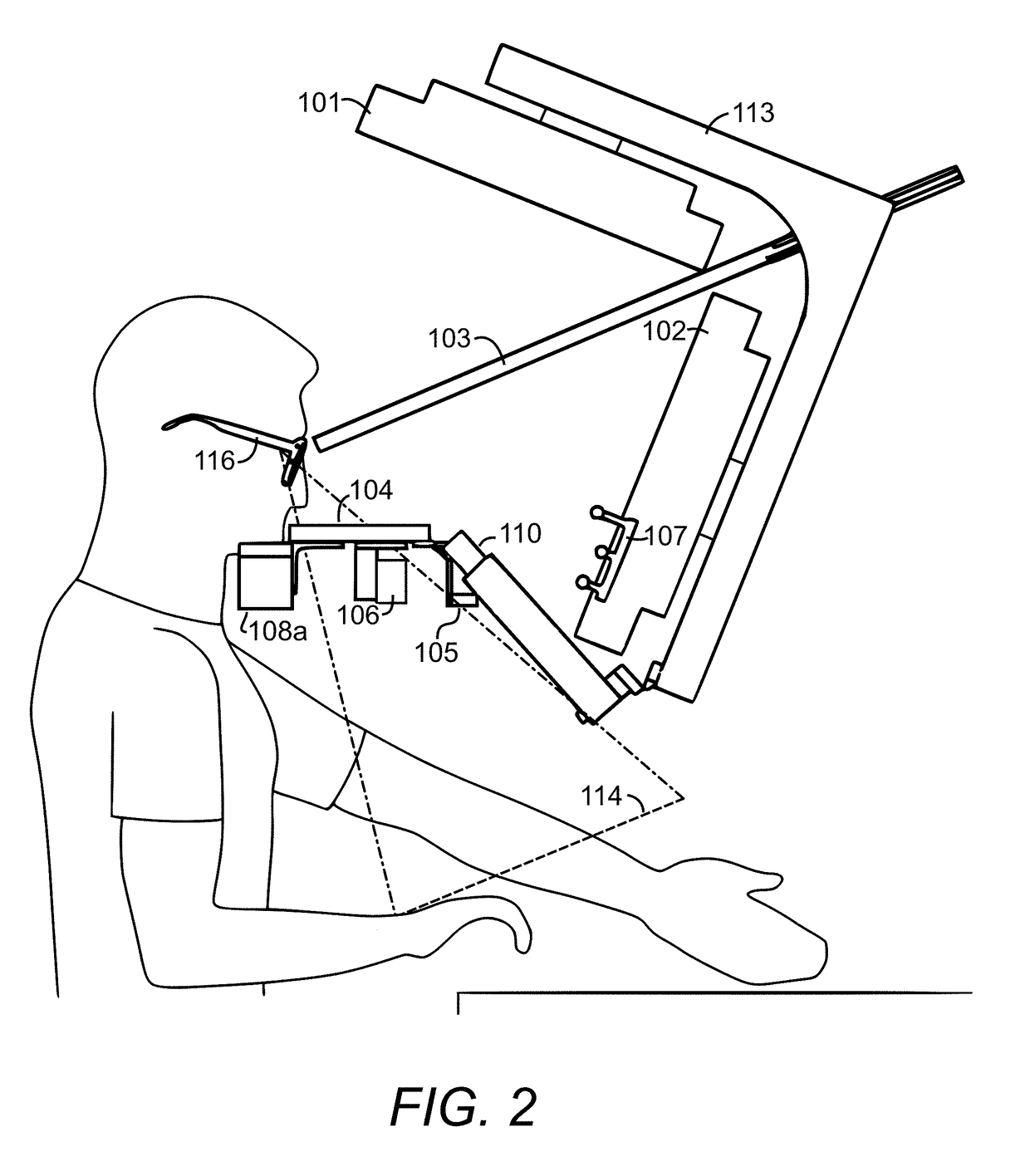
A direct interaction stereoscopic display system that produces an augmented or virtual reality environment. The system comprises one or more displays, a beam combiner, and a mirrored surface to virtually project high-resolution flicker-free stereoscopic 3D imagery into a graphics volume in an open region. Viewpoint tracking is provided enabling motion parallax cues. A user interaction volume co-inhabits the graphics volume and a precise low-latency sensor allows users to directly interact with 3D virtual objects or interfaces without occluding the graphics. An adjustable support frame permits the 3D imagery to be readily positioned in situ with real environments for augmented reality applications. Individual display components may be adjusted to precisely align the 3D imagery with components of real environments for high-precision applications and also to match accommodation-vergence distances to prevent eye strain. The system's modular design and adjustability allows display panel pairs of various sizes and models to be installed.

Description

CROSS-REFERENCE TO RELATED APPLICATIONS[0001]This application claims priority to U.S. Provisional Patent Application Ser. No. 61 / 954,543, filed Mar. 17, 2014, and titled “COMPACT DYNAMICALLY ADJUSTABLE IMMERSIVE STEREOSCOPIC DISPLAY AND DIRECT INTERACTION SYSTEM,” and to U.S. patent application Ser. No. 14 / 660,937, filed Mar. 17, 2015, and titled “STEREOSCOPIC DISPLAY.” The entire contents of both are hereby incorporated by reference.BACKGROUNDTechnical Field[0002]The present disclosure relates generally to interactive three-dimensional (“3D”) displays. More particularly, the present disclosure addresses apparatus, systems, and methods making up a display system with 3D in situ visualization that can maintain the eye's natural accommodation-vergence relationship.Description of Related Art[0003]Interactive 3D display systems have been the subject of a number of developmental efforts over the past 30 years. The prospect of reaching out and directly interacting with virtual content is ...

Claims


Application Information

Patent Timeline
IPC IPC(8): G06F3/01G06T19/20G06T19/00H04N13/04
CPCG06F3/013H04N13/0443H04N13/0434H04N13/0484G06T19/006G06T19/20G06T2219/2004G02B27/283G06F3/011G02B27/0093G06F3/017G06F3/0325G06F3/0425G06F3/03545H04N13/337H04N13/346H04N13/383G02B30/35G02B30/25
Inventor RIEDEL, NICHOLAS V.
Owner SPATIAL INTELLIGENCE LLC
Learn More