
Light diffuser

a technology of light diffuser and light source, which is applied in the field of optical devices, can solve the problems of difficult to easily integrate and design and assemble complex hardware structures, and affect compactness or cosmetics, and achieve the effects of easy adjustment, simple and cheap design, and easy integration in compact luminaires

Active Publication Date: 2017-11-09
KONINKLJIJKE PHILIPS NV
View PDF5 Cites 22 Cited by
  • Summary
  • Abstract
  • Description
  • Claims
  • Application Information

AI Technical Summary

Benefits of technology

The present invention provides a light diffuser that is simple and cheap to design, easy to adjust, and significantly thinner than known diffusers, making it easier to integrate into compact luminaires. Its unique sandwiched structure allows for a low production cost and easy customization through varying the distance between the two plates. Overall, this patent provides a simple and effective way to adjust the light diffusion properties of a light diffuser.

Problems solved by technology

The light diffusers described in the two references above however involve complex hardware structures that are not necessarily easy to design and assemble in production, and further involve active actuators to act on a stretchable structure by means of electrodes.
Also, such structures are relatively thick, which makes it difficult to easily integrate them in luminaires without affecting compactness or cosmetic aspect thereof.

Method used


Image

  • Light diffuser
  • Light diffuser
  • Light diffuser

Examples


Embodiment Construction

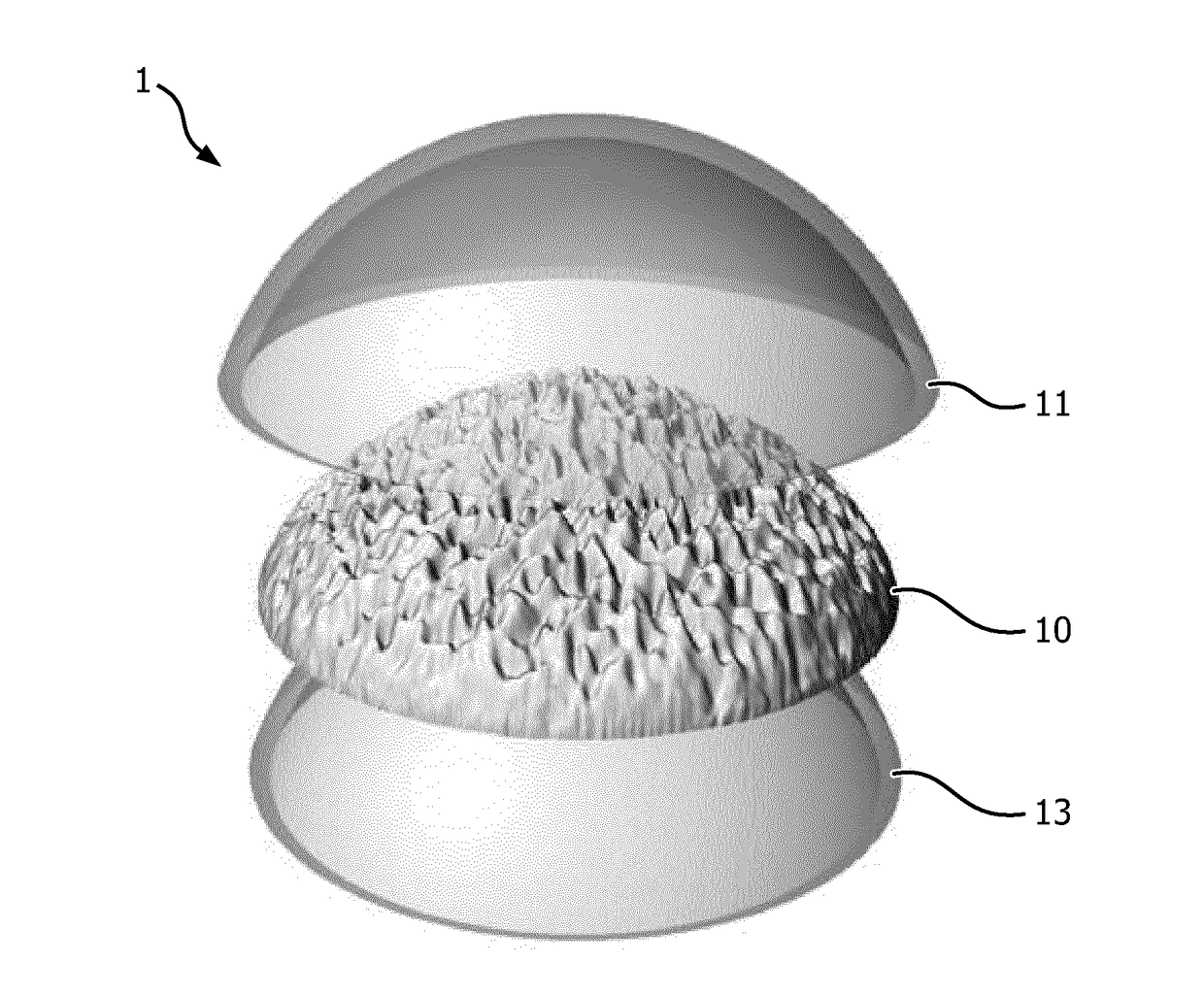
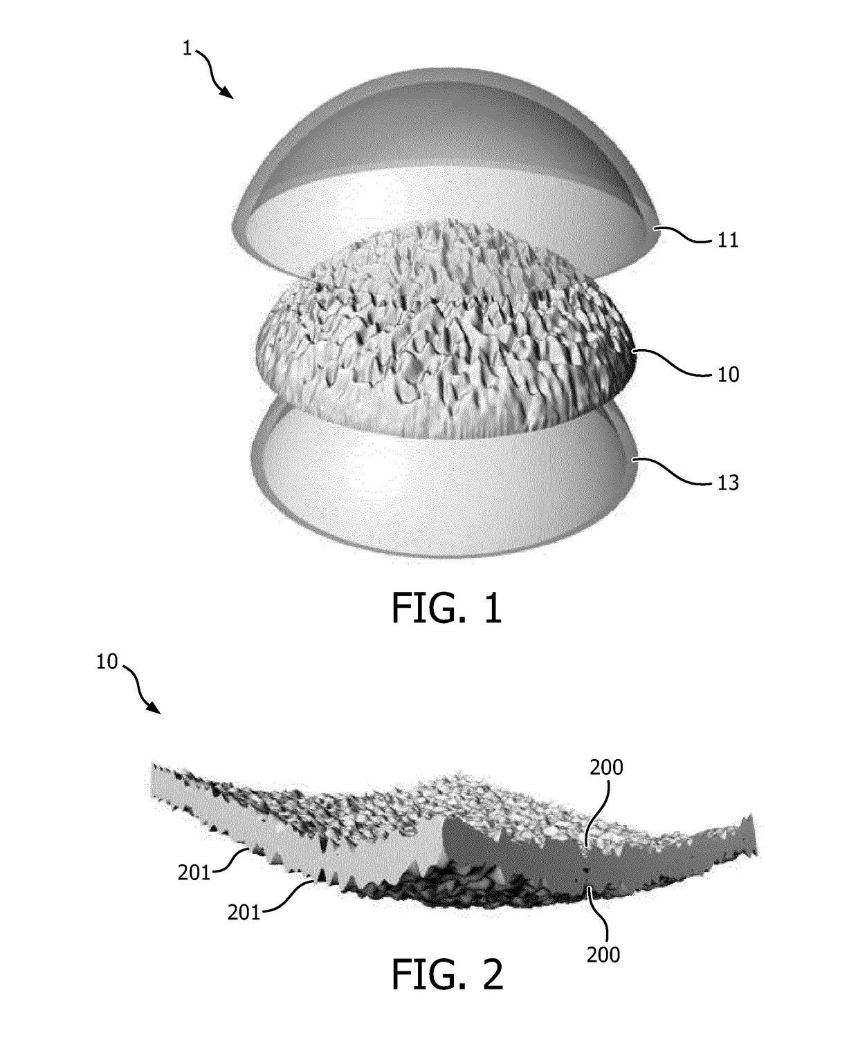
[0034]FIG. 1 shows a perspective view of a first exemplary embodiment of a light diffuser 1 according to the invention. In the non-limiting exemplary embodiment illustrated by FIG. 1, the light diffuser 1 comprises a light diffusing element 10 that is arranged between a first plate 11 and a second plate 13.

[0035]Still in a non-limiting manner, the shape of the first and second plates 11, 13 can be essentially that of a portion of a sphere. Thanks to the flexible structure of the light diffusing element 10, the shape of the light diffusing element 10 adopts the same shape as that of the first and second plates 11, 13, though it is preferred that the global shape of the light diffusing element alone, that is: when not arranged between the first and second plates 11, 13, is essentially similar to the shape of the first and second plates 11, 13.

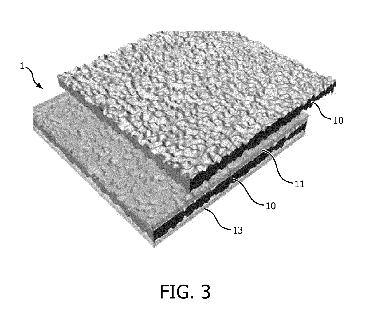
[0036]In other embodiments, such as for instance the second exemplary embodiment described hereinafter in reference to FIG. 3, the first and sec...


PUM


Abstract

The invention relates to a light diffuser (1) comprising a light diffusing element (10), wherein the light diffusing element (10) comprises a flexible translucent material, the light diffuser (1) comprising a first plate (11) and a second plate (13), said first (11) and second (13) plates being rigid and translucent, the light diffusing element (10) being arranged between said first (11) and second (13) plates in such a way that one first face of the light diffusing element (10) is coupled with the first plate (11), and one second face of the light diffusing element (10) is coupled with the second plate (13), at least one of said first or second face comprising a plurality of cavities or excrescences. Such a light diffuser is easily adaptable and can for example be mounted in a luminaire.

Description

FIELD OF THE INVENTION[0001]The present invention relates generally to optical devices, and more particularly to a light diffuser, notably for use in a lighting device, such as a luminaire. In some aspects of the invention, the light diffuser is adapted to have variable light diffusing properties.BACKGROUND[0002]Light diffusers are widely used in lighting devices, for example in luminaires, and allow spreading out or scattering light in a desired manner, to provide a diffused light, for example better adapted to a uniform lighting.[0003]Static and uniform light diffusers are well known, which can be based from diffusing reflectors, or translucent devices for example made with ground glass.[0004]In most applications it can however be desirable that a light diffuser is configured for being easily adaptable, that is: a light diffuser having adjustable light diffusing properties. Such light properties include light diffusion, glare and beam width or full width at half maximum, commonly ...

Claims


Application Information

Patent Timeline
Patent Type & Authority Applications(United States)
IPC IPC(8): G02B5/02F21V5/00F21V14/06
CPCG02B5/0247F21V14/06F21V5/002G02B5/0278G02B5/0221G02B26/004
Inventor MONTAGNE, LOUIS-XAVIER MARIE
Owner KONINKLJIJKE PHILIPS NV
Learn More