Heat-insulation system for liquefied natural gas cargo hold

a technology of heat insulation system and liquefied natural gas, which is applied in the direction of vessel construction, transportation and packaging, vessel details, etc., can solve the problems of limited use of secondary sealing wall sus, wrinkles formed on secondary sealing wall cannot function properly, etc., and achieve high air tightness and competitive price

Inactive Publication Date: 2017-11-09
DAEWOO SHIPBUILDING & MARINE ENG CO LTD
View PDF4 Cites 2 Cited by
  • Summary
  • Abstract
  • Description
  • Claims
  • Application Information

AI Technical Summary

Benefits of technology

[0029]In the heat-insulation system for an LNG cargo containment system according to the present invention, since a securing point at which a secondary sealing wall is connected to a primary sealing wall, that is, a collar stud, is disposed on a line on which an anchor strip is disposed, there are no other securing points on a surface of the secondary sealing wall apart from four sides of the secondary sealing wall. Accordingly, the secondary sealing wall uniformly shrinks upon temperature decrease, whereby wrinkles formed on the secondary sealing wall can function properly.
[0030]That is, since the collar stud is placed on the line on which the anchor strip is disposed, the secondary sealing wall can be prepared against thermal deformation and formed of SUS, whereby the liquefied natural gas cargo containment system with high air-tightness and competitive price can be manufactured.
[0031]In addition, in the heat-insulation system according to the present invention, not only when two membranes are arranged around the collar stud but also when four membranes are arranged, a welding line can be flattened, thereby allowing the membranes to be firmly secured.

Problems solved by technology

Thus, the secondary sealing wall does not uniformly shrink upon temperature decrease such that wrinkles formed on the secondary sealing wall cannot function properly.
Therefore, although SUS has more competitive price than Invar and has superior advantages over Triplex in terms of air-tightness, a typical LNG cargo containment system has a problem in that the use of a secondary sealing wall formed of SUS is limited.

Method used


Image

  • Heat-insulation system for liquefied natural gas cargo hold
  • Heat-insulation system for liquefied natural gas cargo hold
  • Heat-insulation system for liquefied natural gas cargo hold

Examples


first embodiment

[0053]FIG. 5 is a schematic perspective view of a heat-insulation system for an LNG cargo containment system according to the present invention and FIG. 6 is a side sectional view of the heat-insulation system of FIG. 5.

[0054]Referring to FIGS. 5 and 6, a method for manufacturing the heat-insulation system for an LNG cargo containment system according to this embodiment includes: welding one side 311 of a first membrane 310 to an outer edge of an upper surface of an anchor strip 500 and welding another side 312 of the first membrane 310 to a central portion of the upper surface of the anchor strip 500; forming a stepped portion having the same height as the first membrane 310 at one edge of the second membrane 320; placing one edge of the first membrane 310 under the stepped portion of the second membrane 320 and welding one side 321 of the second membrane 320 to an upper surface of the first membrane 310; welding another side 322 of the second membrane 320 to the central portion of...

second embodiment

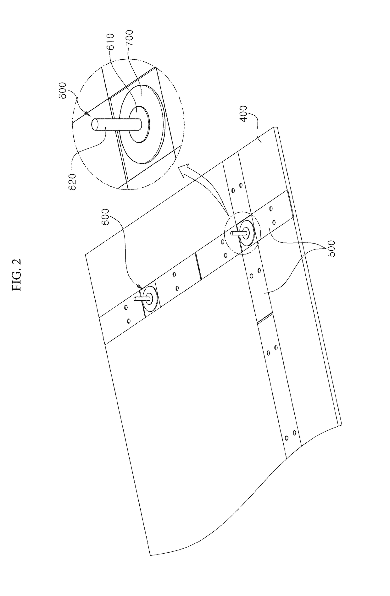
[0057]FIG. 7 is a schematic side sectional view of a heat-insulation system for an LNG cargo containment system according to the present invention and FIG. 8 is a plan view of the heat-insulation system of FIG. 7.

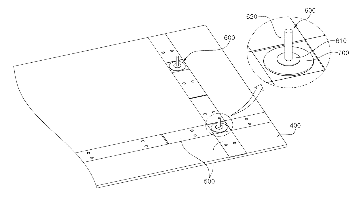
[0058]Referring to FIGS. 7 and 8, a method for manufacturing the heat-insulation system for an LNG cargo containment system according to this embodiment includes: beveling a vertex 315, 325, 335 or 345 of each of first to fourth membranes 310, 320, 330, 340; disposing a vertical portion 620 of a collar stud 600 perpendicular to a setting plate 700; welding each side of the first membrane 310 to an upper surface of an anchor strip 500 and welding a beveled portion 315 at the vertex of the first membrane 310 to an upper surface of the setting plate 700; placing the third membrane 330 diagonally opposite the first membrane 310; welding each side of the third membrane 330 to the upper surface of the anchor strip 500 and welding a beveled portion 335 at the vertex of the third m...

third embodiment

[0063]FIG. 9 is a schematic side sectional view of a heat-insulation system for an LNG cargo containment system according to the present invention and FIG. 10 is a plan view of the heat-insulation system of FIG. 9.

[0064]Referring to FIGS. 9 and 10, a method for manufacturing the heat-insulation system for an LNG cargo containment system according to this embodiment includes: beveling a vertex 315, 325, 335, or 345 of each of first to fourth membranes 310, 320, 330, 340; placing a beveled portion 315 at the vertex where the first membrane 310 meets an upper surface of a setting plate 700 and welding each side of the first membrane 310 to an upper surface of an anchor strip 500; placing the third membrane 330 diagonally opposite the first membrane 310 such that a beveled portion 335 at the vertex of the third membrane 330 is located on the upper surface of the setting plate 700; welding each side of the third membrane 330 to the upper surface of the anchor strip 500; placing a beveled...


PUM


Abstract

Disclosed is a heat-insulation system for a liquefied natural gas cargo hold, which comprises a primary sealing wall, a secondary sealing wall, and a secondary heat-insulating layer, and is applied to a liquefied natural gas cargo hold. The heat-insulation system for a liquefied natural gas cargo hold comprises a collar stud installed on a line on the upper surface of the secondary heat-insulating layer where an anchor strip is installed.

Description

TECHNICAL FIELD[0001]The present invention relates to a heat-insulation system for a liquefied natural gas cargo containment system, and more particularly, to a heat-insulation system for a liquefied natural gas cargo containment system including a secondary sealing wall disposed on a secondary heat-insulating wall.BACKGROUND ART[0002]With growing global interest in eco-friendly businesses, demand for clean fuel, which can replace existing energy sources such as petroleum and coal, is increasing. In this situation, natural gas is used in various fields as a main energy source having cleanliness, stability and convenience. Unlike in the US and Europe, where natural gas is directly supplied through pipelines, Korea introduced liquefied natural gas (LNG) obtained by liquefying natural gas at an extremely low temperature and has supplied LNG to consumers. Thus, the demand for a cargo containment system (CCS) for storing LNG is increasing along with the increase in domestic natural gas d...

Claims


Application Information

Patent Timeline
Patent Type & Authority Applications(United States)
IPC IPC(8): B63B25/16F17C3/04B63B9/06F17C3/02
CPCB63B25/16B63B9/06F17C3/027F17C3/04F17C2270/0107F17C2209/221F17C2221/033F17C2260/01F17C2203/03B65D90/06F17C1/12B65D90/022B63B73/43
Inventor PARK, KWANG JUNKANG, JOONG KYOO
Owner DAEWOO SHIPBUILDING & MARINE ENG CO LTD
Why Eureka
Try Eureka