Exhaust Gas Aftertreatment Device And Exhaust Gas Aftertreatment Method

a technology of exhaust gas aftertreatment and exhaust gas, which is applied in the direction of gas chambers, machines/engines, mechanical equipment, etc., can solve the problems of inability to realize satisfactory exhaust sound damping, strong tendency to corrosion, and movable parts are located in the exhaust-gas flow, so as to improve the sound damping effect of the exhaust-gas aftertreatment device and achieve effective sound damping

Active Publication Date: 2017-11-02
DORING ANDREAS
View PDF11 Cites 0 Cited by
  • Summary
  • Abstract
  • Description
  • Claims
  • Application Information

AI Technical Summary

Benefits of technology

The exhaust-gas aftertreatment device described in this patent allows for the flexible setting of the sound damping action to a wide range of exhaust sound frequencies, making it effective even in internal combustion engines operated at different engine speeds. The device includes a sound damping chamber that can adjust the fill level of fluid or pourable solid therein based on the frequency of the exhaust gas to be damped. The U-shaped chamber design with two sub-chambers further improves the sound damping action. Additionally, the device can also include emission control devices, such as catalytic converters and exhaust gas scrubber, to provide both sound damping and emission control, while reducing space requirements.

Problems solved by technology

Silencers of this type have a narrow-banded damping action however, so that in particular in the case of engines which are operated with variable speed and therefore have different exhaust frequencies, it is not possible to realize a satisfactory exhaust sound damping.
Silencers of this type have the disadvantage however, that movable parts are located in the exhaust-gas flow, which have a strong tendency to corrosion in particular if the internal combustion engine, the exhaust sound of which is to be damped, is operated using high-sulphur fuels.
Furthermore, in silencers of this type, only a plurality of narrow-banded frequency ranges can be subjected to an effective sound damping, an infinitely variable adaptation of the damping action of the silencer to different frequency ranges of the exhaust sound to be damped is not possible.

Method used


Image

  • Exhaust Gas Aftertreatment Device And Exhaust Gas Aftertreatment Method
  • Exhaust Gas Aftertreatment Device And Exhaust Gas Aftertreatment Method
  • Exhaust Gas Aftertreatment Device And Exhaust Gas Aftertreatment Method

Examples


Embodiment Construction

[0019]The invention relates to an exhaust-gas aftertreatment device for an internal combustion engine, particularly for a marine diesel internal combustion engine operated using heavy fuel oil.

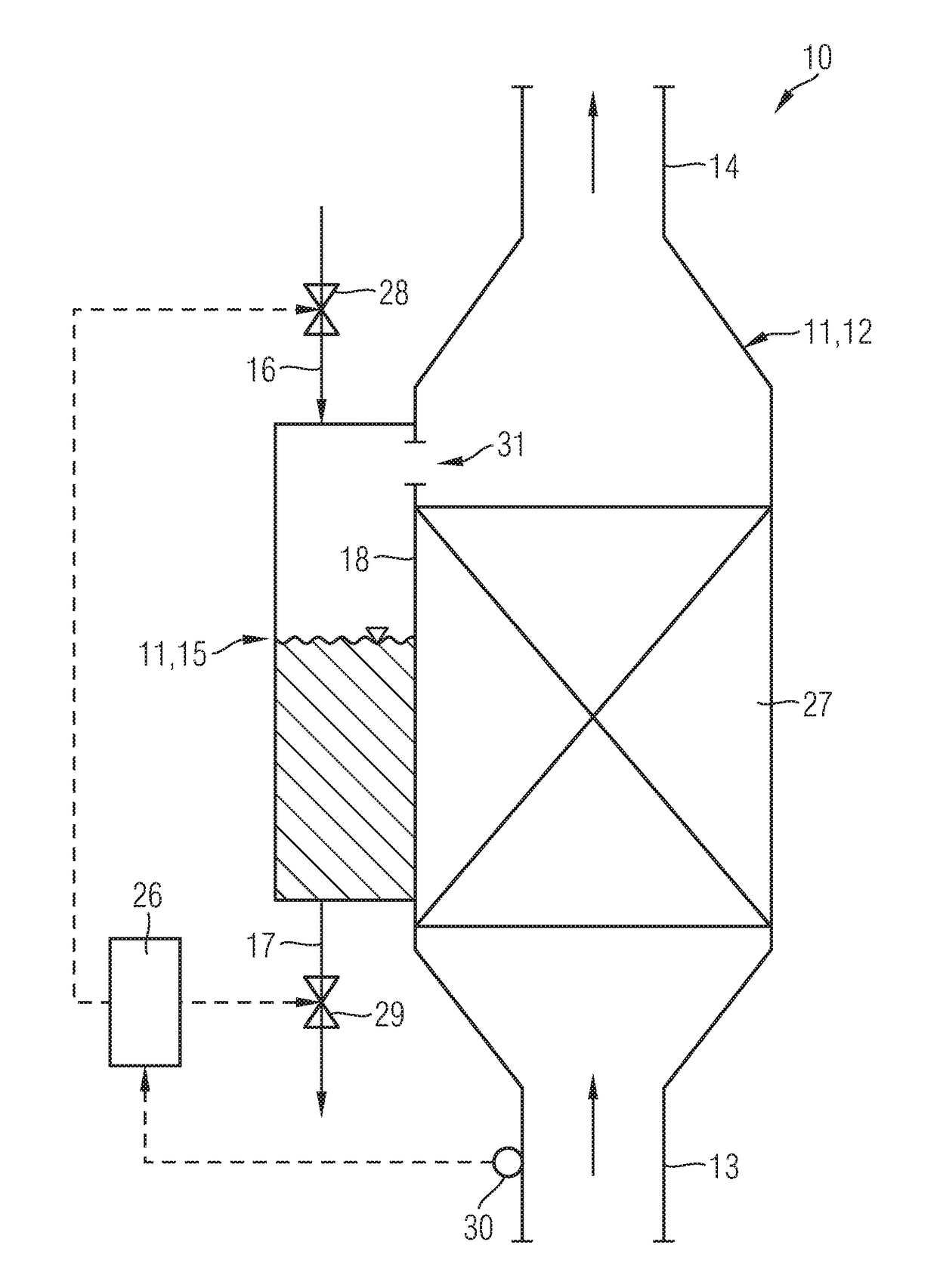
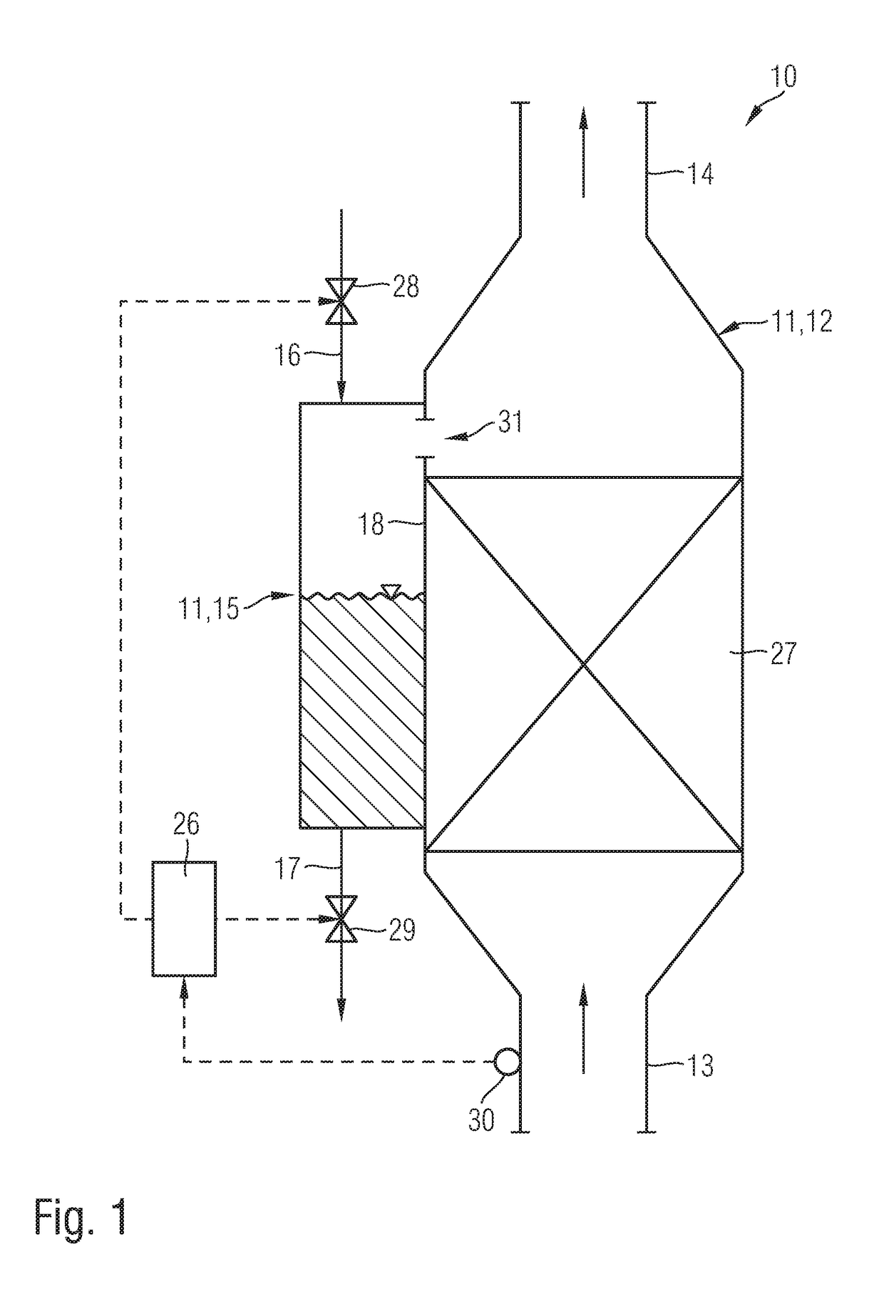
[0020]FIG. 1 shows a schematic illustration of a first exemplary embodiment of an exhaust-gas aftertreatment device 10 according to the invention for an internal combustion engine, particularly for a marine diesel internal combustion engine operated using heavy fuel oil.

[0021]The exhaust-gas aftertreatment device 10 comprises a housing 11. The housing 11 defines an exhaust-gas chamber 12 on one side, through which exhaust gas flows continuously, into which exhaust-gas chamber exhaust gas flows via an inlet 13 and out of which exhaust gas flows via an outlet 14, and a sound damping chamber 15 on the other side.

[0022]The sound damping chamber 15 is coupled with the exhaust-gas chamber 12.

[0023]A fluid, particularly a liquid, or a pourable solid, particularly a granulated material, is accommodate...


PUM


Abstract

An exhaust-gas aftertreatment device (10) for an internal combustion engine, particularly for a marine diesel internal combustion engine operated using heavy fuel oil, includes a housing (11); an exhaust-gas chamber (12) defined by the housing (11), for permitting exhaust gas to flow continuously through the housing (11), an inlet (13) for permitting exhaust gas to flow into the housing and an outlet (14) for permitting exhaust gas to flow out of the housing (11); a sound damping chamber (15), defined by the housing (11) and coupled with the exhaust-gas chamber (12). The sound dampening chamber (15) is constructed to receive a fluid or a pourable solid at a fill level depending on the frequency of an exhaust sound to be damped.

Description

PRIORITY CLAIM[0001]This is a U.S. national stage of application No. PCT / EP2015 / 074365, filed on 21 Oct. 2015. Priority is claimed on the following application(s): Country: Germany, Application No.: 10 2014 016 448.9, filed: 6 Nov. 2014, the content of which is / are incorporated herein by reference in its entirety.FIELD OF THE INVENTION[0002]The invention relates to an exhaust-gas aftertreatment device and a method for exhaust-gas aftertreatment.BACKGROUND OF THE INVENTION[0003]It is known from practice that both emission control devices such as catalytic converters or exhaust gas scrubbers and silencers can be arranged downstream of an internal combustion engine as exhaust-gas aftertreatment modules. The catalytic converters are used in particular for nitrogen removal and / or desulphurization of the exhaust gas and therefore the reduction of nitrogen-oxide emissions and sulphur-oxide emissions. The silencers are used for noise reduction and thus reducing sound emissions.[0004]Silence...

Claims


Application Information

Patent Timeline
Patent Type & Authority Applications(United States)
IPC IPC(8): F01N1/06F01N1/02F01N1/16
CPCF01N1/06F01N1/161F01N1/02F01N2490/12F01N2230/02F01N2230/04F01N2590/02F01N1/023
Inventor DORING, ANDREAS
Owner DORING ANDREAS
Why Eureka
Try Eureka