Rear window roller blind system

a roller blind and rear window technology, applied in the field of roller blind systems, can solve the problems of insufficient rigidity of the connection of the clasp to the shelf portion, difficult assembly, etc., and achieve the effects of simple production, high degree of stability, and high degree of stability

Inactive Publication Date: 2014-11-27
BOS
View PDF8 Cites 0 Cited by
  • Summary
  • Abstract
  • Description
  • Claims
  • Application Information

AI Technical Summary

Benefits of technology

[0021]The invention further also relates to a production method for producing a roller blind system of the above-described type. In this instance, this production method is characterized by the specific feature that the vessel member is produced as a plastics component starting from a planar blank by means of a thermal forming process. This forming process may in particular be a stamping process, in which the heated blank is brought into the desired three-dimensional shape. This production method is, on the one hand, cost-effective. It is further advantageous since it enables the simple production of the three-dimensional shaping, which results in a high degree of stability. The selective influence of the properties of the vessel member by means of the use of a multi-layered blank or a blank of composite material is also possible.

Problems solved by technology

However, the problem also exists here that the two shelf portions which are consequently connected to each other only in the region of narrow webs are movable relative to each other and consequently make assembly more difficult.
However, this connection of the clasps to the shelf portions is not of a sufficiently rigid type for the shelf to be able to be handled as a common structural unit during assembly.
It has also been a problem up to the present time with existing configurations that the through-slot between the shelf portions also allows noise to penetrate into the passenger space.
However, it also relates to the noise which is generated by other vehicle components in the rear region of a vehicle and which can reach as far as a region below the parcel shelf and from there can reach the passenger inner space through the though-slot.

Method used


Image

  • Rear window roller blind system
  • Rear window roller blind system
  • Rear window roller blind system

Examples


Embodiment Construction

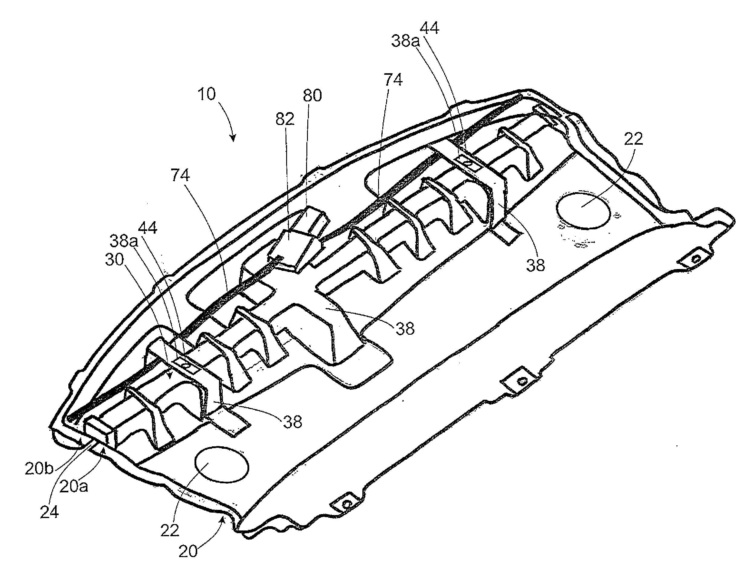
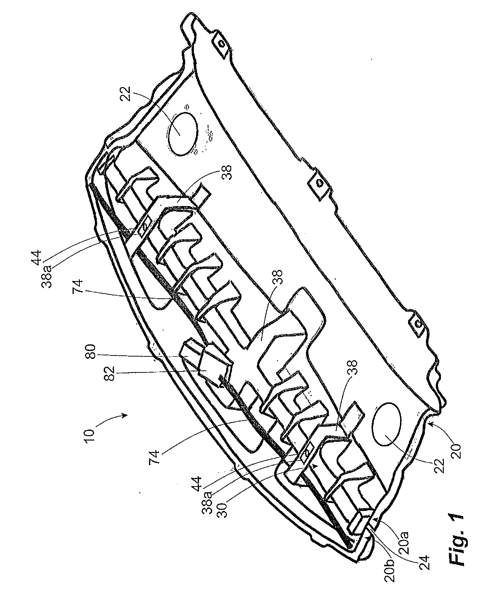
[0028]FIG. 1 shows an exemplary embodiment of a roller blind system according to the invention. This can be seen in FIG. 1 as a perspective view from below.

[0029]The roller blind system 10 has a substantially rigid shelf 20, which comprises two shelf portions 20a, 20b which are rigid per se and which are produced as separate components. They form by means of the upper side thereof which cannot be seen in FIG. 1 the parcel shelf of a vehicle, which is arranged behind the rear seats of the vehicle. They may further perform other functions. In the illustrated exemplary embodiment, for instance, the front shelf portion 20a is also the carrier of loudspeakers of an audio system and has to this end recesses 22 for loudspeakers.

[0030]The two shelf portions 20a, 20b are not directly connected to each other since the slot 24 provided therebetween acts as a through-slot for a flexible surface structure 54 of the roller blind system 10. Therefore, the connection of the two shelf portions 20a, ...


PUM

PropertyMeasurementUnit
flexibleaaaaaaaaaa
surface structureaaaaaaaaaa
surface areaaaaaaaaaaa

Abstract

A roller blind system for a rear window of a motor vehicle, having a roller blind, a roller blind shaft rotatable about a main axis and a sheet-like structure which, in a stowed state, is wound on the roller blind shaft and which, in a functional state, is partially unwound from the roller blind shaft, and having an shelf for arranging in the rear region of the motor vehicle. The shelf has front and rear shelf portions separated from one another by a passage slot through which the sheet-like structure is moved during a movement from the stowed state into the functional state. The two shelf portions are connected to one another via a trough body and the roller blind shaft is arranged within the trough body and is rotatably mounted by bearing blocks which are fastened to, or are an integral part of, the trough body.

Description

FIELD OF APPLICATION AND PRIOR ART[0001]The invention relates to a roller blind system for covering a rear window of a motor vehicle having a roller blind, comprising a roller blind shaft which can be rotated about a main axis and a flexible surface structure which is wound on the roller blind shaft in a storage state and which is at least partially unwound from the roller blind shaft in an operating state, and having a planar shelf which is intended to be arranged in the rear region of the motor vehicle and which comprises a front and a rear shelf portion, which each form a part-portion of the shelf and which are separated from each other by means of a through-slot through which the surface structure is moved during transfer from the storage state into the operating state.[0002]Roller blind systems of the generic type are generally known from the prior art. The roller blind which these roller blind systems comprise conventionally has a roller blind shaft and a surface structure whi...

Claims


Application Information

Patent Timeline
Patent Type & Authority Applications(United States)
IPC IPC(8): B60J1/18B29C51/26
CPCB60J1/18B29L2031/719B29C51/266B29C51/264B60J1/2038B60J1/2063B60J1/208
Inventor BUEHL, OLAFWEINBRENNER, HARRY
Owner BOS
Why Eureka
Try Eureka