
Printing apparatus and printing method

a printing apparatus and printing method technology, applied in printing, other printing apparatus, etc., can solve the problems of inability to easily eliminate the adhesion of mist-like liquid to the discharge head, and various problems caused by electrification of recording medium, so as to reduce uneven destaticization of recording medium, suppress adhesion of mist-like liquid, and reduce the effect of nois

Active Publication Date: 2017-10-26
SEIKO EPSON CORP
View PDF2 Cites 0 Cited by
  • Summary
  • Abstract
  • Description
  • Claims
  • Application Information

AI Technical Summary

Benefits of technology

The patent describes a printing apparatus that has two steps to destaticize the recording medium, which prevents liquid from sticking to the discharge head. The first step uses an AC voltage to apply ions to the recording medium, but this can cause uneven destaticization. The second step uses a smaller AC voltage to further destaticize the medium and mitigate uneven destaticization. This results in a more efficient and effective process to prevent liquid adhesion to the discharge head.

Problems solved by technology

However, in the printing apparatus, there is a concern that various problems caused by electrification of the recording medium occur.
In addition, since the sticking of the recording medium to the driving roller influences the detection result of tension of the recording medium, there is a case where the tension control of the recording medium is not appropriately performed (first problem).
In addition, there is also a situation in which the adhesion of the mist-like liquid to the discharge head cannot be easily eliminated by destaticization of the recording medium.
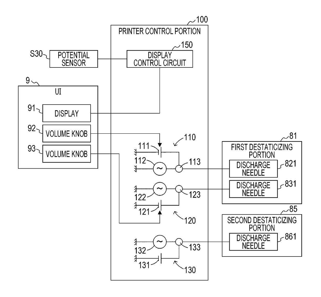
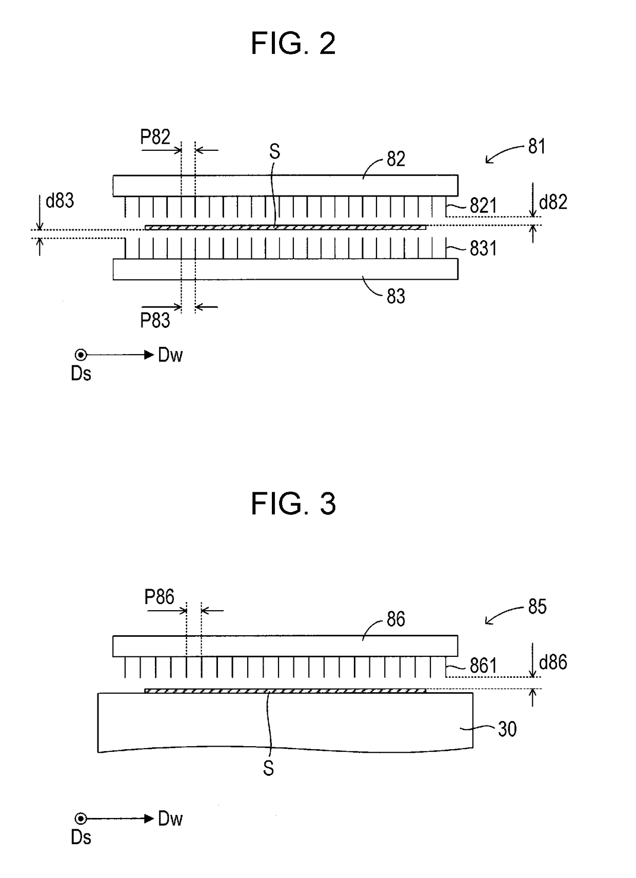
However, since there is a tendency for a large number of ions to be imparted being deviated to a part which opposes the electrode in the recording medium, there is a case where uneven destaticization caused by arrangement of the electrodes is generated and the mist-like liquid adheres to a location that corresponds to the uneven destaticization in the discharge head (second problem).
In addition, since an ion balance is not appropriate, there is a case where the recording medium supported by the supporting member cannot be sufficiently destaticized and mist-like liquid adheres to the discharge head which opposes the supporting member (third problem).
In other words, in a case where the front surface of the supporting member has conductivity, there is a concern that the ions generated by the destaticizing portion are oriented toward a part which is not hidden in the recording medium in the supporting member, and the ions cannot be definitely imparted to the recording medium.
Therefore, a large difference in applying amount of ions between a part at which the ions are tightly imparted and a part at which the ions are sparsely imparted is generated, and uneven destaticization is likely to be generated in the recording medium destaticized by the first destaticizing portion.
However, the amplitude of the AC voltage generated in the recording medium by the AC voltage applied to the electrode of the second destaticizing portion is relatively small.

Method used


Image

  • Printing apparatus and printing method
  • Printing apparatus and printing method
  • Printing apparatus and printing method

Examples


Embodiment Construction

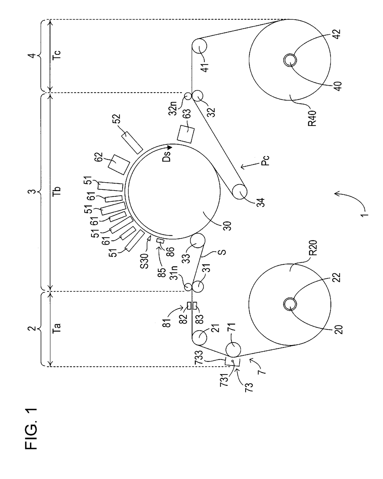
[0037]FIG. 1 a front view schematically illustrating an example of an inner configuration of a printer which employs the invention. As illustrated in FIG. 1, in a printer 1, one sheet S (web) of which both ends are wound around a delivery shaft 20 and a winding shaft 40 in a rolled shape stretches between the delivery shaft 20 and the winding shaft 40, and the sheet S is transported to the winding shaft 40 from the delivery shaft 20 along a transport path Pc which stretches in this manner. In other words, each of both ends of the sheet S is wound in a rolled shape, a delivery roll R20 and a winding roll R40 are formed, and the sheet S is transported in a roll-to-roll manner along a transport direction Ds toward the winding roll R40 that is pivotally supported by the winding shaft 40 from the delivery roll R20 which is pivotally supported by the delivery shaft 20.

[0038]In addition, in the printer 1, an image is recorded on the sheet S transported in the transport direction Ds. The ty...


PUM


Abstract

There is provided a printing apparatus including: a driving roller which drives a recording medium in a predetermined direction by rotation thereof; a supporting member which supports the recording medium further on the downstream side in the predetermined direction than the driving roller; a discharge head which is provided to oppose the supporting member and discharges liquid to the recording medium supported by the supporting member; a tension control portion which adjusts tension of the recording medium supported by the supporting member by controlling tension of the recording medium based on a result of detecting tension of the recording medium further on the downstream side in the predetermined direction than the driving roller; and a first destaticizing portion which destaticizes the recording medium further on the upstream side in the predetermined direction than the driving roller.

Description

BACKGROUND1. Technical Field[0001]The present invention relates to a technology for destaticizing a recording medium which is used in printing.2. Related Art[0002]A printing apparatus (printer) described in JP-A-2014-184665 includes a recording head disposed to oppose a rotation drum, and prints an image on a recording medium by discharging ink from the recording head while supporting the recording medium (sheet) by the rotation drum. However, in the printing apparatus, there is a concern that various problems caused by electrification of the recording medium occur.[0003]As an example, there is a case where influence on a tension control of the recording medium is generated. In other words, in JP-A-2014-184665, a driving roller is provided further on an upstream side in a transport direction of the recording medium than a supporting member (rotation drum) which supports the recording medium. In addition, by controlling tension of the recording medium based on a result of detecting t...

Claims


Application Information

Patent Timeline
Patent Type & Authority Applications(United States)
IPC IPC(8): B41J15/16
CPCB41J15/16
Inventor TOYAMA, HIROSHIKATAGAMI, SATORU
Owner SEIKO EPSON CORP
Learn More