
Plastic processing screw

a technology of plastic processing screw and screw body, which is applied in the field of screw body, can solve the problems of defect rate in manufacturing parts and quality of resulting parts, and achieve the effect of maximizing the versatility of screw body

Active Publication Date: 2017-10-26
DRAY SR ROBERT F
View PDF3 Cites 3 Cited by
  • Summary
  • Abstract
  • Description
  • Claims
  • Application Information

AI Technical Summary

Benefits of technology

The present invention provides an improved plastic processing screw that can be used with different plastic formulations. The screw has a triangular land and a continuous groove in its surface, which functions as a barrier member. The barrier member can be adjusted and is located either above or below the land and groove. The selected angle of the rolling blade is 45 degrees. This design allows for efficient processing of plastic materials using the screw.

Problems solved by technology

The suitability (or lack thereof) of a particular screw design for the particular plastic formulation it processes can have significant impact on the quality of the resulting part and the defect rate in manufacturing those parts.

Method used


Image

  • Plastic processing screw
  • Plastic processing screw
  • Plastic processing screw

Examples


Embodiment Construction

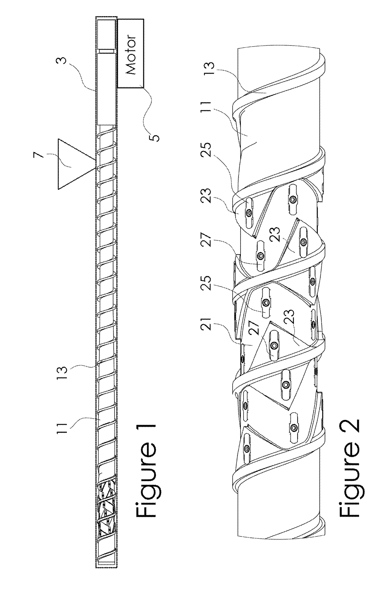
[0018]Referring now to the Figures, and particularly to FIG. 1, a schematic depiction of an injection-molding or extrusion apparatus 1 of the type contemplated in the present invention is illustrated. Apparatus 1 comprises a heated containment barrel 3, a motor 5, and a feed hopper 7. A flighted screw 11 is rotated by motor 5 in containment barrel 3. Plastic or polymer pellets are fed into barrel 3 from hopper 7. Rotation of screw 11 in barrel 3, combined with the application of heat from electric (resistance) heaters in barrel, melts and mixes the plastic pellets together. Screw 11 may also be coupled to a hydraulic ram (not shown), which reciprocates screw 11 to close a non-return valve and, acting as a plunger, discharge or inject a shot or volume of mixed and melted plastic into a mold (not shown). If configured for extrusion, no ram is present and pressure generated by the screw is used to move the melted and mixed plastic to an extrusion die or in combination with other extrus...


PUM

PropertyMeasurementUnit
angleaaaaaaaaaa
lengthaaaaaaaaaa
outer diameteraaaaaaaaaa

Abstract

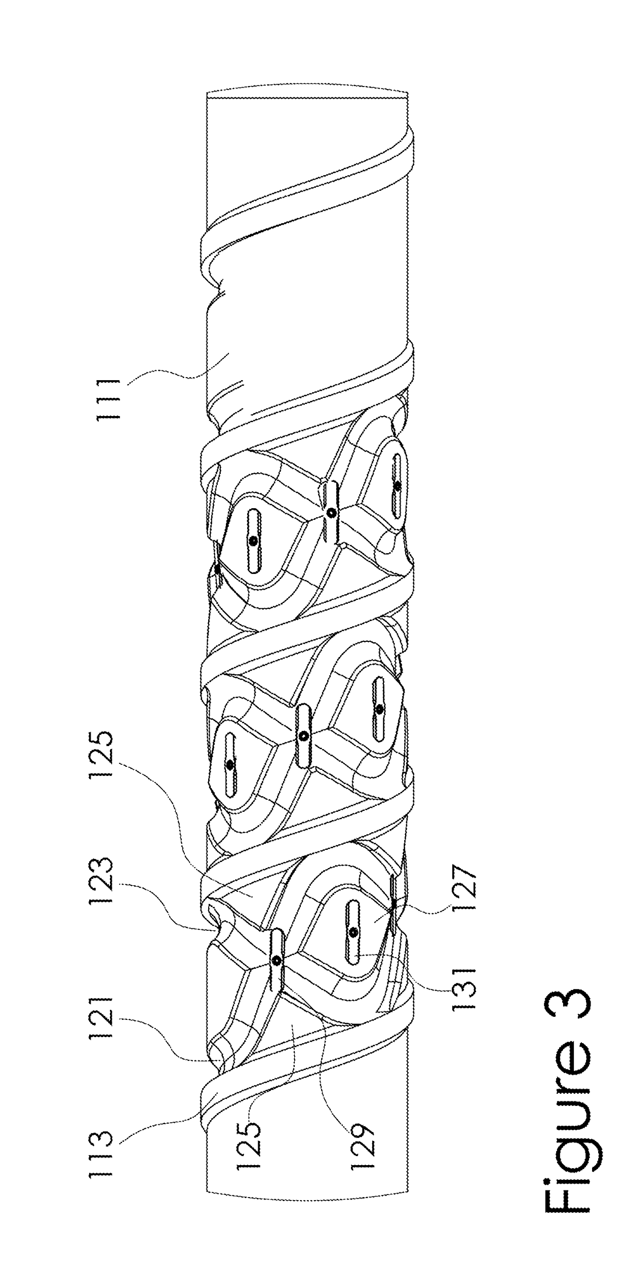
An improved screw has a shaft having a surface and a central axis and at least one flight extending helically along the surface of the shaft in successive turns. A continuous groove is formed in the surface of the shaft and extends between successive, pushing and trailing, turns of the flight at a selected angle greater than zero. The groove defines at least one generally triangular land having a base aligned with a pushing turn of the flight and an apex between successive turns of the flight. The groove also defines another generally triangular land having a base aligned with a trailing turn of the flight. Barriers or dams may be provided on the lands and in the grooves. A second continuous groove may also be formed in the surface of the shaft.

Description

BACKGROUND OF THE INVENTIONField of the Invention[0001]The present invention relates generally to the flighted screws used in injection-molding, extrusion, and similar apparatus. More particularly, the present invention relates to improvements in such screws to increase their versatility by increasing the number of polymer formulations the screw is capable of optimally processing.Summary of the Prior Art[0002]In injection-molding and extrusion of polymer or plastic resin (the terms “plastic” and “polymer” are used herein synonymously and interchangeably) material, a feed screw with a helical flight or flights on its outer surface rotates in a heated containment barrel. Plastic pellets are fed into the apparatus at one end and the application of heat, friction, and shear forces to the pellets melts and mixes the pellets into a polymer shot (or volume) suitable for injection. The screw then is reciprocated (moved forward), closing a non-return valve, and acts as a plunger to inject th...

Claims


Application Information

Patent Timeline
Patent Type & Authority Applications(United States)
IPC IPC(8): B29C47/60B29B7/42B29C48/56B29C48/16B29C48/395B29C48/54B29C48/55B29C48/565
CPCB29C47/6043B29C47/6031B29C47/385B29B7/42B29C47/6037B29B7/429B29C48/16B29C48/565B29C48/56B29C48/54B29C48/55B29C48/397
Inventor DRAY, SR., ROBERT F.
Owner DRAY SR ROBERT F
Learn More