Coil component
a technology of coil components and components, applied in the direction of transformer/inductances, inductances, magnetic cores of transformers/inductances, etc., can solve the problems of reducing manufacturing costs and avoiding manual operation, so as to improve heat radiation characteristics, and improve heat radiation characteristics efficiently
- Summary
- Abstract
- Description
- Claims
- Application Information
AI Technical Summary
Benefits of technology
Problems solved by technology
Method used
Image

Examples
first embodiment
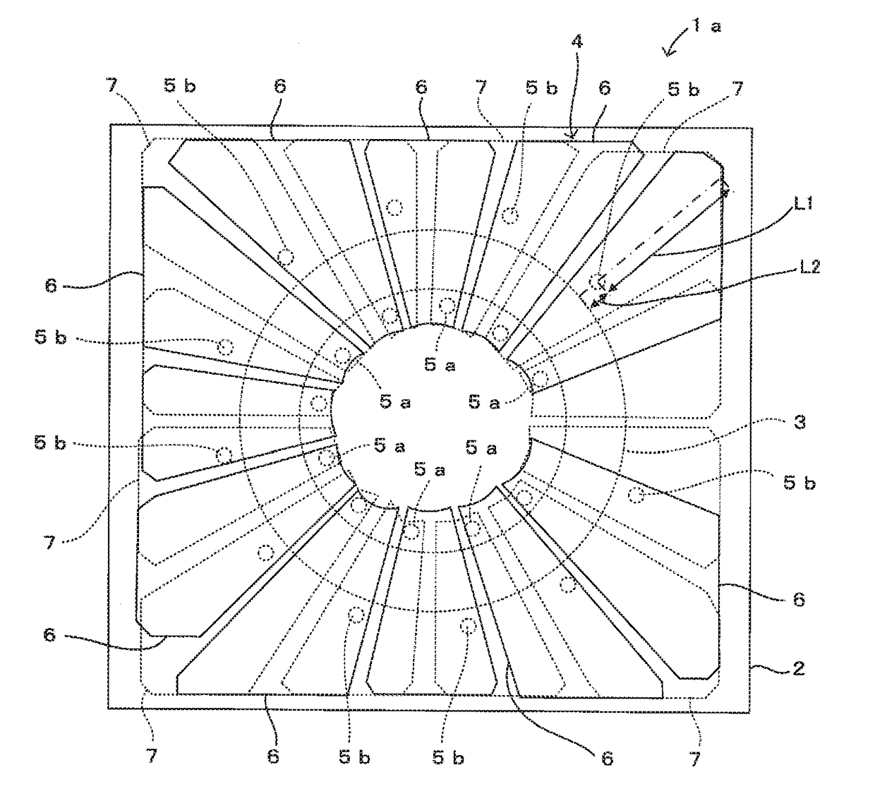
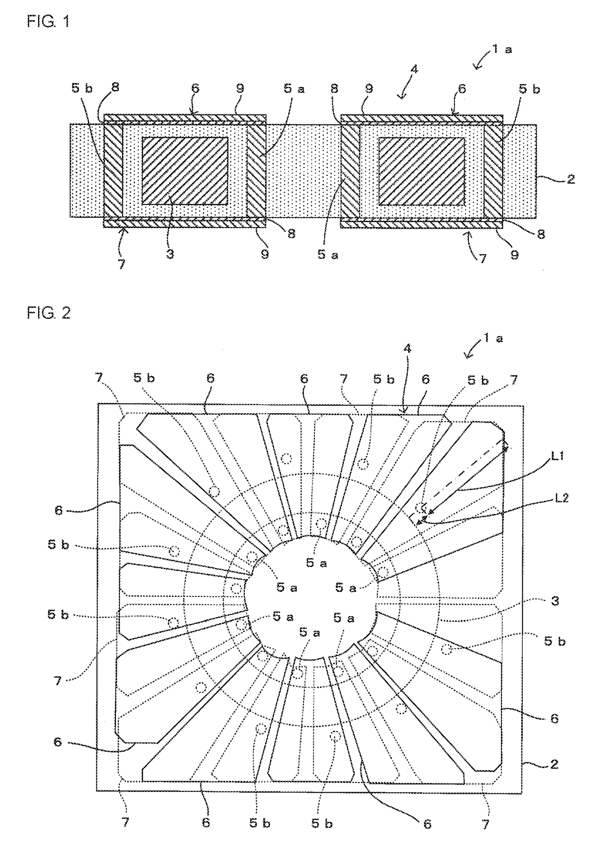
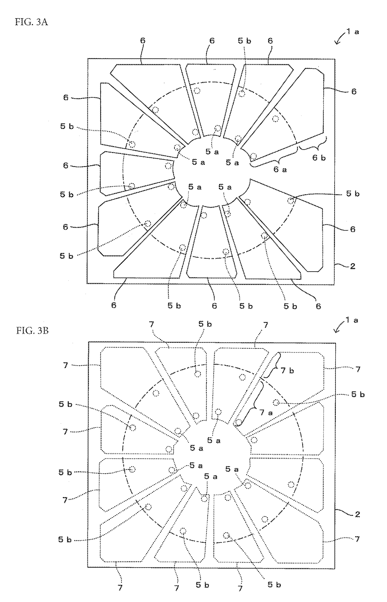
[0029]A coil component 1a according to a first embodiment of the present disclosure will be described with reference to FIGS. 1 to 3A and 3B. FIG. 1 is a sectional view of the coil component 1a, FIG. 2 is a plan view of the coil component 1a, and FIGS. 3A and 3B explain upper and lower wiring patterns 6 and 7. FIG. 3A is a plan view of the coil component 1a from which a coil core 3 and the lower wiring patterns 7 are removed, and FIG. 3B is a plan view of the coil component 1a from which the coil core 3 and the upper wiring patterns 6 are removed.
[0030]As illustrated in FIGS. 1 to 3A and 3B, the coil component 1a according to this embodiment includes an insulating layer 2 having a coil core 3 embedded therein and a coil electrode 4 wound around the coil core 3, and is mounted in an electronic device, such as a cellular phone, using a high-frequency signal.
[0031]For example, the insulating layer 2 is made of resin such as epoxy resin, and has a predetermined thickness to cover the co...
second embodiment
[0063]A coil component 1b according to a second embodiment of the present disclosure will be described with reference to FIG. 5. FIG. 5 is a plan view of the coil component 1b from which a coil core 3 and upper wiring patterns 6 are removed, and corresponds to FIG. 3B.
[0064]The coil component 1b of this embodiment is different from the coil component 1a of the first embodiment described with reference to FIGS. 1 to 3A and 3B in that each lower wiring pattern 7 further includes a heat radiating portion 7c (corresponding to “first heat radiating portion” in the present disclosure) extended from an end portion of a wiring portion 7a (end portion close to an inner metal pin 5a) toward an inner peripheral side of the coil core 3 in addition to a heat radiating portion 7b extended toward an outer peripheral side of the wiring portion 7a, as illustrated in FIG. 5. Since other structures are the same as those of the coil component 1a of the first embodiment, they are denoted by the same ref...
third embodiment
[0067]A coil component 1c according to a third embodiment of the present disclosure will be described with reference to FIG. 6. FIG. 6 is a plan view of the coil component 1c from which a coil core 3 and upper wiring patterns 6 are removed, and corresponds to FIG. 3B.
[0068]The coil component 1c of this embodiment is different from the coil component 1a of the first embodiment described with reference to FIGS. 1 to 3A and 3B in that only lower wiring patterns 7 disposed near four corners of a lower surface of an insulating layer 2, of a plurality of lower wiring patterns 7, have heat radiating portions 7b, as illustrated in FIG. 6. Since other structures are the same as those of the coil component 1a of the first embodiment, they are denoted by the same reference numerals, and descriptions thereof are skipped.
[0069]In this case, in each of four lower wiring patterns 7 closest to four corners of the lower surface of the insulating layer2, a heat radiating portion 7b is extended from a...
PUM
| Property | Measurement | Unit |
|---|---|---|
| distance | aaaaa | aaaaa |
| heat | aaaaa | aaaaa |
| frequency | aaaaa | aaaaa |
Abstract
Description
Claims
Application Information
 - R&D
- Intellectual Property
- Life Sciences
- Materials
- Tech Scout
- Unparalleled Data Quality
- Higher Quality Content
- 60% Fewer Hallucinations
Browse by: Latest US Patents, China's latest patents, Technical Efficacy Thesaurus, Application Domain, Technology Topic, Popular Technical Reports.
© 2025 PatSnap. All rights reserved.Legal|Privacy policy|Modern Slavery Act Transparency Statement|Sitemap|About US| Contact US: help@patsnap.com