Axial Turbine Engine Compressor De-Icing Blade

a technology of compressor and turbine engine, which is applied in the direction of engine control, jet propulsion plant, electrical equipment, etc., can solve the problems of real ice blocks which represent potential risks, add weight to the turbojet, and affect the proper operation

Inactive Publication Date: 2017-10-19
SAFRAN AERO BOOSTERS SA
View PDF8 Cites 8 Cited by
  • Summary
  • Abstract
  • Description
  • Claims
  • Application Information

AI Technical Summary

Benefits of technology

[0048]The present application is advantageous since the use of a thermistor allows both for a heating electrical conductor and a temperature sensor. As a result, a single fixing operation allows two functions to be added to the vane. The production cost and the production time are reduced.
[0049]The present application is accurate and effective. It measures as closely as possible the temperature of the vane and provides thereto, still as closely as possible, the necessary calories. The thermistor is therefore suitable for providing a double function on a face directly affected by the ice.
[0050]The present application makes it possible to aim for automation of the de-icing device. Using a negative coefficient (NTC) thermistor, it is possible to increase the resistance thereof when the temperature decreases, such that the calories obtained by Joule effect increase for the same powering. The control means can then be simplified and possibly removed.
[0051]According to another approach, it can be considered that the layer of ice provides a thermal insulation. As a result, when the temperature should fall due to the altitude but the temperature measured by the thermistor does not consequently fall, more calories must be provided. In this context, a positive coefficient (PTC) thermistor can be used with the aim of self-control.

Problems solved by technology

Of course, this ice adds weight to the turbojet, but above all it affects the proper operation thereof since it changes the profiles of the surfaces guiding the core flow.
This development can result in real blocks of ice which represent potential risks.
Indeed, in the case where they detach, the compressor that sucks them in deteriorates.
In particular, the rotor blades thereof which hit against them are damaged; and possibly break.
This de-icing system, although effective, remains complex.
The cost thereof remains high in addition to it being bulky.

Method used


Image

  • Axial Turbine Engine Compressor De-Icing Blade
  • Axial Turbine Engine Compressor De-Icing Blade
  • Axial Turbine Engine Compressor De-Icing Blade

Examples


Embodiment Construction

[0014]The present application aims to at least one of the problems presented by the prior art. More precisely, the objective of the present application is to simplify the de-icing of a turbine engine vane. Another objective of the present application is to propose a solution that is compact, economical, robust, and easy to install on an axial turbine engine vane.

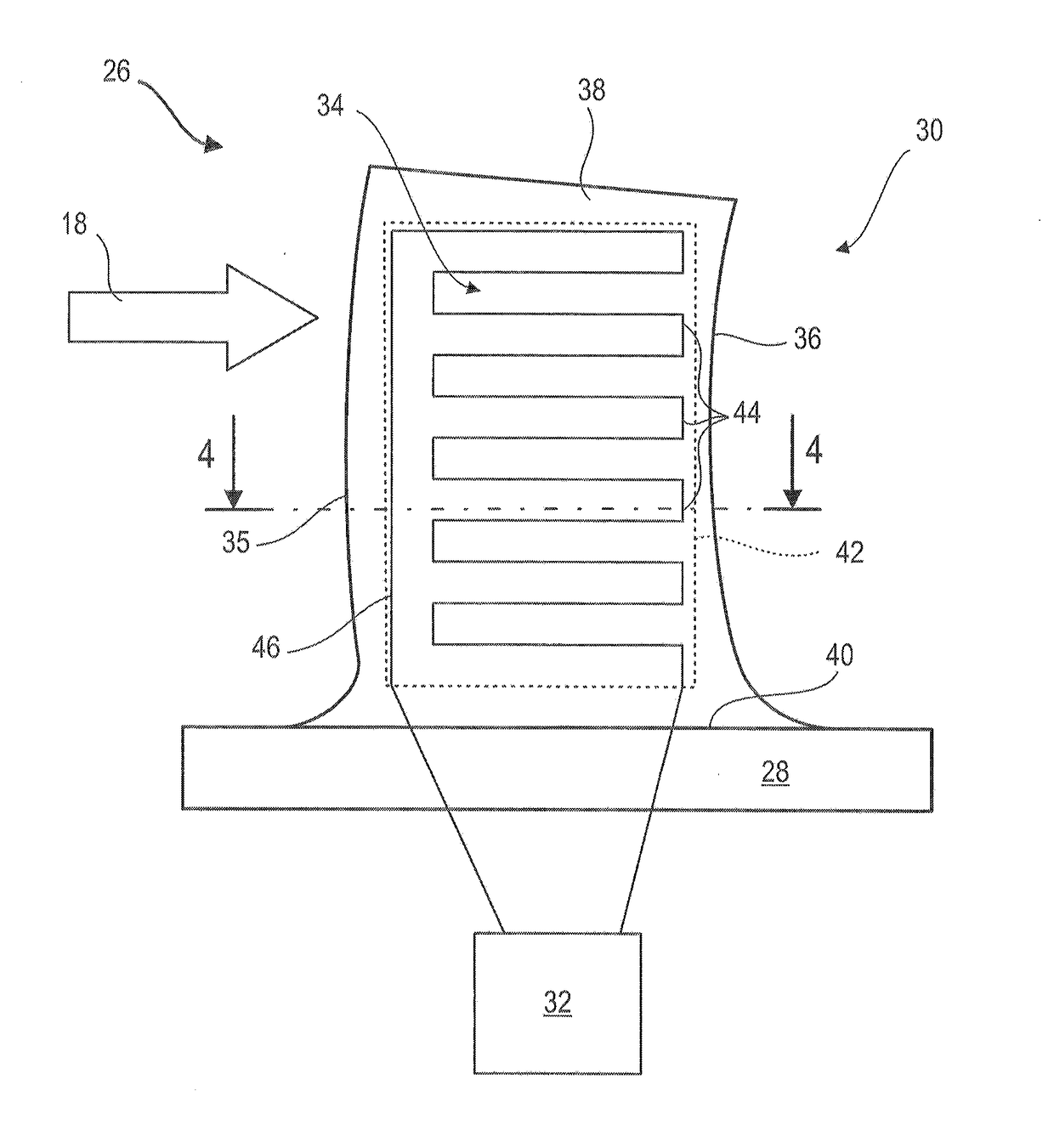
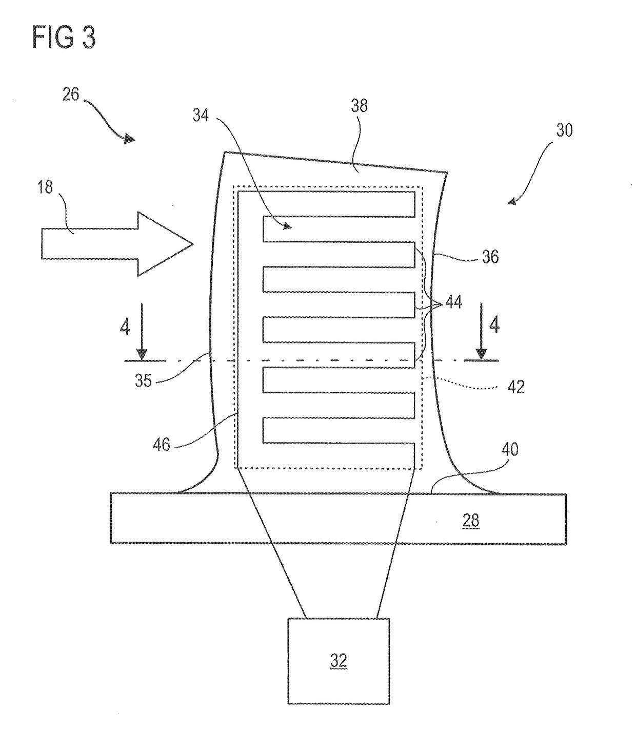
[0015]The subject matter of the present application is a turbine engine vane, particularly an axial turbine engine stator vane, the vane comprising: a leading edge; a trailing edge; a intrados surface and an extrados surface which extend from the leading edge to the trailing edge; and an electric de-icing device; characterized in that the de-icing device includes a thermistor forming a heating electrical track suitable for de-icing the vane.

[0016]According to an advantageous embodiment of the present application, the thermistor is arranged on the extrados surface and / or on the intrados surface of the vane.

[0017]According to ...


PUM


Abstract

An aeroplane turbojet low-pressure compressor vane includes a leading edge, a trailing edge, a surface, and an extrados surface which extend from the leading edge to the trailing edge. To combat the presence and the formation of ice, the vane is provided with an electric de-icing device with a thermistor. The thermistor forms a heating electrical track suitable for de-icing the vane. The present application also proposes a method for producing a turbine engine vane.

Description

[0001]This application claims priority under 35 U.S.C. §119 to Belgium Patent Application No. 2016 / 5241, filed Apr. 8, 2016, titled “Axial Turbine Engine Compressor De-Icing Blade,” which is incorporated herein by reference for all purposes.BACKGROUND1. Field of the Application[0002]The present application relates to the field of electric de-icing of turbine engine vanes. The present application also relates to a turbine engine compressor, and a turbine engine like an aeroplane turbojet or an aircraft turbo-prop. The present application also proposes a method for producing a turbine engine vane with an electric de-icing device.2. Description of Related Art[0003]A turbojet is subject to the phenomenon of icing during the operation thereof. Low temperatures combined with the presence of humidity in the air promote the formation of ice on the internal operational surfaces. Of course, this ice adds weight to the turbojet, but above all it affects the proper operation thereof since it ch...

Claims


Application Information

Patent Timeline
Patent Type & Authority Applications(United States)
IPC IPC(8): F01D25/02F01D9/04H05B1/02F01D25/10
CPCF01D25/02F01D9/041F01D25/10H05B1/02F05D2220/323F05D2240/12F05D2250/183F05D2270/303F05D2230/60F05D2250/182F01D5/08F04D29/582F02C7/047
Inventor VALLINO, FREDERIC
Owner SAFRAN AERO BOOSTERS SA
Why Eureka
Try Eureka