
Iridescent badges for vehicles and methods of making the same

a technology of iridescent badges and badges, applied in the field of iridescent badges and trim, can solve the problems of increased badge cost, high cost of such vehicles, and significant added cost of these materials

Inactive Publication Date: 2017-10-19
FORD GLOBAL TECH LLC
View PDF7 Cites 12 Cited by
  • Summary
  • Abstract
  • Description
  • Claims
  • Application Information

AI Technical Summary

Benefits of technology

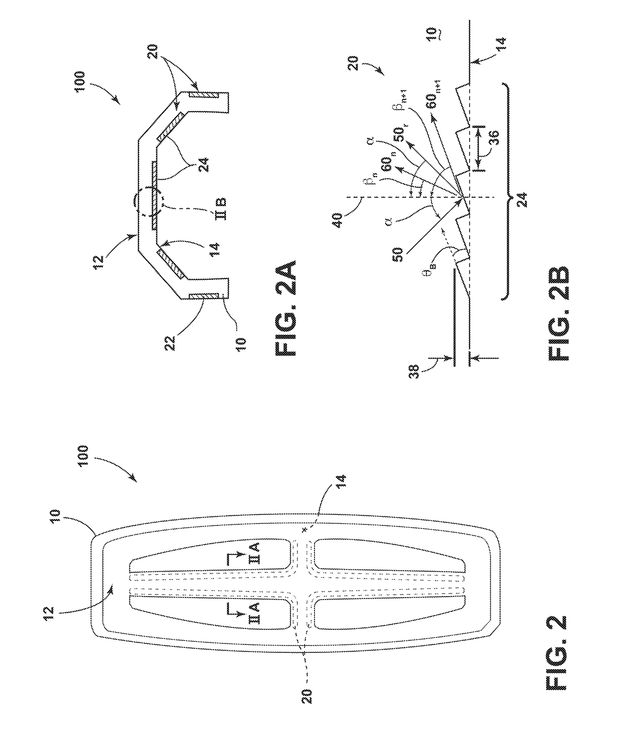
The present invention provides an iridescent vehicle badge having a non-planar shape and comprising an interior and exterior surface. The badge includes at least one surface that is non-planar and comprises a diffraction grating having a thickness from 250 nm to 1000 nm and a period from 50 nm to 5 microns. This results in a badge that has a unique and visually appealing appearance. The method of making the badge involves forming a mold with mold surfaces corresponding to the interior and exterior surfaces of the badge, ablating at least one of the mold surfaces to form a diffraction grating mold surface, and forming the badge with a diffraction grating having a thickness from 250 nm to 1000 nm and a period from 50 nm to 5 microns in the mold surfaces with a polymeric material. The technical effects of this invention include an improved aesthetic appearance and improved manufacturing process for vehicle badges.

Problems solved by technology

Car enthusiasts and owners of luxury and high-end vehicles are continually demanding new aesthetics that justify, at least in part, the high cost of such vehicles.
Nevertheless, merely adding jewels and precious metals to conventional badges will significantly increase the cost of the badge, and all but the most cost-insensitive car enthusiasts will likely object to the significant added cost of these materials.
In addition, the inclusion of jewels and / or precious metals into a vehicular badge increases the likelihood that it will be removed by thieves as a target of relative opportunity.
Unfortunately, the results of such approaches are not promising.

Method used


Image

  • Iridescent badges for vehicles and methods of making the same
  • Iridescent badges for vehicles and methods of making the same
  • Iridescent badges for vehicles and methods of making the same

Examples


Embodiment Construction

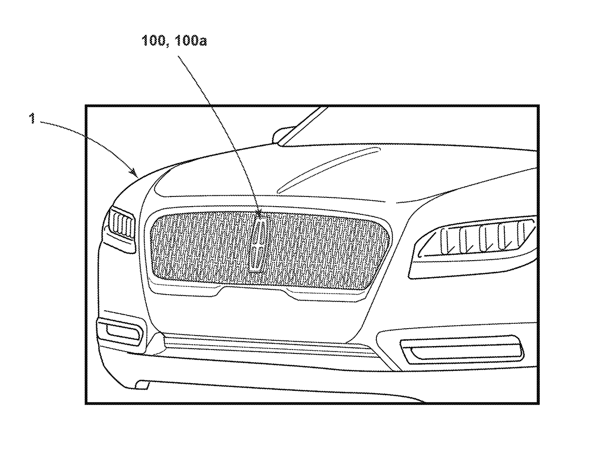
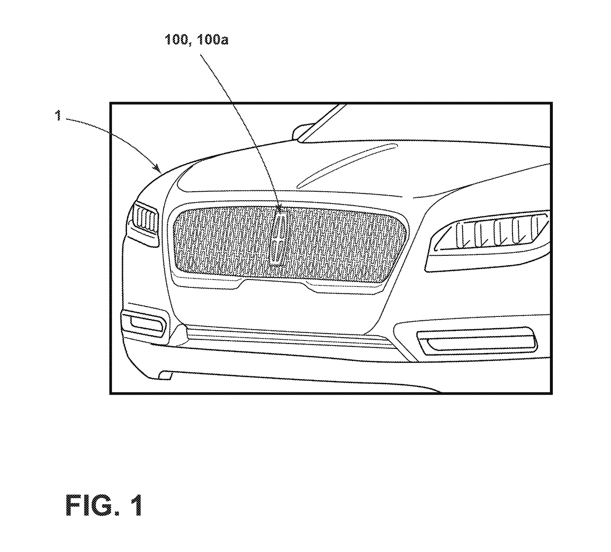
[0019]For purposes of description herein, the terms “upper,”“lower,”“right,”“left,”“rear,”“front,”“vertical,”“horizontal,”“interior,”“exterior,”“vehicle forward,”“vehicle rearward,” and derivatives thereof shall relate to the invention as oriented in FIG. 1. However, the invention may assume various alternative orientations, except where expressly specified to the contrary. Also, the specific devices and assemblies illustrated in the attached drawings and described in the following specification are simply exemplary embodiments of the inventive concepts defined in the appended claims. Hence, specific dimensions and other physical characteristics relating to the embodiments disclosed herein are not to be considered as limiting, unless the claims expressly state otherwise.

[0020]Described in this disclosure are iridescent badges, trim and other exterior surfaces (collectively, “iridescent vehicular elements”) for vehicles (and methods of making the same). The iridescent vehicular eleme...


PUM

PropertyMeasurementUnit
thicknessaaaaaaaaaa
thicknessaaaaaaaaaa
thicknessaaaaaaaaaa

Abstract

An iridescent vehicle badge (and methods for making it) that includes a translucent, polymeric badge having a non-planar shape and comprising an interior and an exterior surface. Further, at least one of the surfaces of the badge comprises a plurality of diffraction gratings that are integral with the badge, each having a thickness from 250 nm to 1000 nm and a varying period from 50 nm to 5 microns. In some cases, the thickness can range from 500 nm to 750 nm. The period, in some cases, can vary within a set of discrete values in one or more portions of the at least one of the surfaces of the badge, e.g., from 150 nm to 400 nm.

Description

FIELD OF THE INVENTION[0001]The present invention generally relates to iridescent badges, trim and other exterior surfaces for vehicles and methods of making the same, particularly automotive badges with a jewel-like appearance.BACKGROUND OF THE INVENTION[0002]Car enthusiasts and owners of luxury and high-end vehicles are continually demanding new aesthetics that justify, at least in part, the high cost of such vehicles. Vehicle badges can be designed to reflect the luxury and high-end nature of particular vehicle models. For example, certain vehicle models can be more desirable to car enthusiasts and owners with a badge having a jewel-like appearance.[0003]The direct incorporation of jewels and / or precious metals into a vehicle badge can satisfy these needs in some respects. These elements might be encapsulated within a translucent badge for a luxurious aesthetic. Nevertheless, merely adding jewels and precious metals to conventional badges will significantly increase the cost of t...

Claims


Application Information

Patent Timeline
Patent Type & Authority Applications(United States)
IPC IPC(8): B60R13/00G09F3/02B29C33/38B29C33/40B29C33/42B29D11/00
CPCB60R13/005G09F3/02B29C33/424B29C33/3842B29C33/40B29D11/00769G02B5/1857G02B27/44B29C45/263B29C45/372B29L2031/744G09F19/12G09F21/04G09F2007/1882
Inventor DELLOCK, PAUL KENNETHSALTER, STUART C.KARMO, TALATMUSLEH, MICHAELWALAWENDER, CHESTER STANISLAUS
Owner FORD GLOBAL TECH LLC
Learn More