Top Sheet For Absorbent Articles
- Summary
- Abstract
- Description
- Claims
- Application Information
AI Technical Summary
Benefits of technology
Problems solved by technology
Method used
Image
Examples
first embodiment
1. When Inside of Small Region is Filled with Fiber
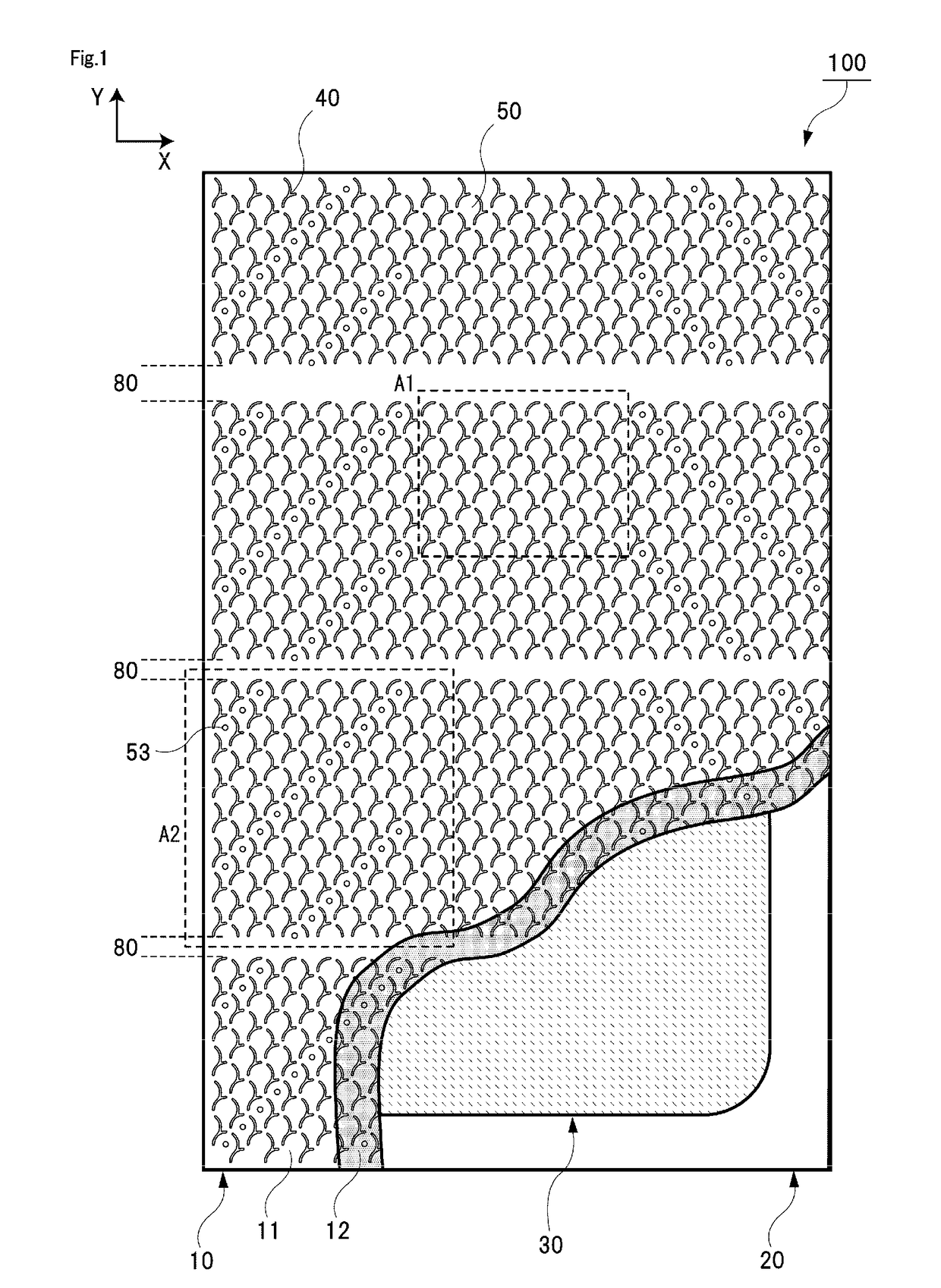
[0069]A description will be given of a first embodiment of a disposable diaper according to the invention with reference to FIG. 1 to FIG. 7(c). The first embodiment is a mode in which an inside of a small region 52 of an upper layer sheet 11 described below is filled with fiber.
[0070]FIG. 1 is a plan view of an absorbent article 100 according to the first embodiment of the invention viewed from a skin facing surface side. For example, the absorbent article 100 according to the invention may be used for a disposable diaper, a urine pad, a panty liner, a light incontinence pad, and a sanitary napkin. FIG. 1 schematically illustrates an internal structure of the absorbent article 100. As illustrated in FIG. 1, the absorbent article 100 includes a top sheet 10, a back sheet 20, and an absorber 30. The top sheet 10 is a sheet disposed on a skin facing surface side of the absorber 30 to directly come into contact with a skin of a wearer...
second embodiment
2. When Small Region Holds Space Therein
[0114]Next, a description will be given of a second embodiment of the disposable diaper according to the invention with reference to FIG. 8(a) to FIG. 10. The second embodiment corresponds to a mode in which the small region 52 of the upper layer sheet 11 holds a space therein. In description of the second embodiment, a similar configuration to that of the above-described first embodiment will not be described, and a difference from the first embodiment will be described in detail.
[0115]FIGS. 7(a) to 7(c) illustrate cross-sectional views of a top sheet according to the second embodiment, and correspond to FIGS. 5(a) to 5(c). FIG. 7(b) is a cross-section view taken along Y-Y line illustrated in FIG. 7(a), and FIG. 7(c) is a cross-section view taken along X-X line illustrated in FIG. 7(a). As illustrated in FIGS. 7(b) and 7(c), the large region 51 and the small region 52 of the non-joining portion 50 are formed in dome shapes that hold spaces t...
first modified example
4-1. First Modified Example
[0163]FIG. 15 illustrates a first modified example of the embossing pattern formed on the top sheet. As illustrated in FIG. 15, in the first modified example, a joining portion group including a plurality of joining portions 40 that surrounds one non-joining portion 50 has an asymmetric shape similarly to the embodiment of FIG. 14. In more detail, in Modified Example 1, the joining portion group satisfies requirements below.
[0164](1) The joining portion group is not in line symmetry with respect to the symmetry axis H along the width direction (front-rear line asymmetry).
[0165](2) The joining portion group is not in line symmetry with respect to the symmetry axis V along the longitudinal direction (left-right line asymmetry).
[0166](3) The joining portion group is not in rotational symmetry using the center C of the non-joining portion 50 as a center of symmetry (rotational asymmetry).
[0167](4) All the plurality of joining portions 40 included in the joinin...
PUM
 Abstract
Description
Claims
Application Information
 - R&D
- Intellectual Property
- Life Sciences
- Materials
- Tech Scout
- Unparalleled Data Quality
- Higher Quality Content
- 60% Fewer Hallucinations
Browse by: Latest US Patents, China's latest patents, Technical Efficacy Thesaurus, Application Domain, Technology Topic, Popular Technical Reports.
© 2025 PatSnap. All rights reserved.Legal|Privacy policy|Modern Slavery Act Transparency Statement|Sitemap|About US| Contact US: help@patsnap.com


