
LED driver circuit

a driver circuit and driver technology, applied in the direction of lighting devices, electrical devices, light sources, etc., can solve the problems of not being able to modulate light easily, and achieve the effect of easy control and management of emission colors

Active Publication Date: 2017-10-05
CITIZEN ELECTRONICS CO LTD +1
View PDF0 Cites 11 Cited by
  • Summary
  • Abstract
  • Description
  • Claims
  • Application Information

AI Technical Summary

Benefits of technology

The present invention provides an LED driver circuit that can easily adjust the color temperature and red tinge by modulating light. By controlling the turning-on of different LED groups, the first color temperature is dominant during low-rate dimming, while the second color temperature is dominant during 100% dimming. This makes it easy to achieve the desired color temperature. The LED driver circuit also allows for easy control of the red tinge by switching between LEDs that contribute to low and high color temperatures.

Problems solved by technology

It has not been easy to modulate light so as to obtain a desired color temperature by combining a plurality of LED groups having different light emission behavior by dimming.

Method used


Image

  • LED driver circuit
  • LED driver circuit
  • LED driver circuit

Examples


Embodiment Construction

[0033]An LED driver circuit according to embodiments of the present invention will be described below with reference to the drawings. However, it should be noted that the technical scope of the present invention is not limited to these embodiments but extends to the inventions described in claims and their equivalents.

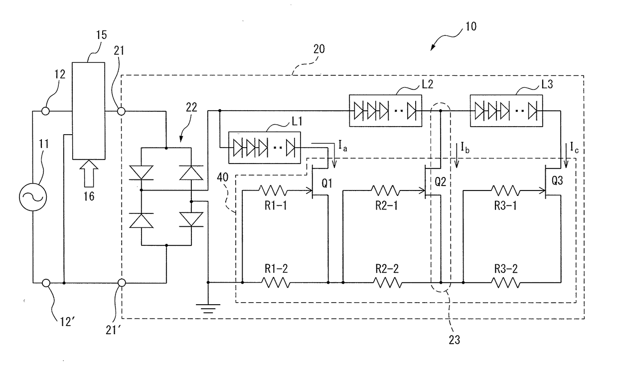
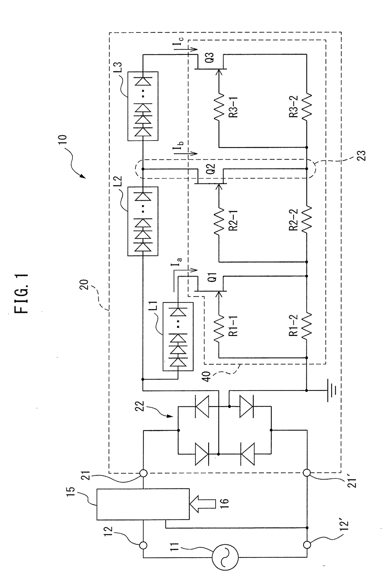
[0034]FIG. 1 is a circuit diagram of an LED driver system 10 according to an embodiment of the present invention.

[0035]The LED driver system 10 is composed of connection terminals 12 and 12′ connected to a commercial AC source (AC 120 V) 11, a phase control dimmer unit 15, an LED driver circuit 20, and the like.

[0036]The LED driver circuit 20 includes an anode terminal 21, a cathode terminal 21′, a full-wave rectifier diode bridge circuit 22, a first LED group L1 in which 10 first LEDs are connected in series, a second LED group L2 in which 35 second LEDs are connected in series, a third LED group L3 in which 10 second LEDs are connected in series, a bypass pathway 23,...


PUM


Abstract

The purpose of the present invention is to provide an LED driving circuit with which it is possible to easily manage the color temperature by adjusting light. An LED driving circuit, characterized in having: a first LED group in which a plurality of first LEDs are serially connected, the first LED group contributing to emission of light having a first color temperature; a second LED group in which a plurality of second LEDs are serially connected, the second LED group contributing to emission of light having a second color temperature; a third LED group in which a plurality of second LEDs are serially connected, the second LED group contributing to emission of light having the second color temperature; and a control unit for switching, in response to an increase in a rectified output voltage, from illumination of only the first LED group to illumination of only the second LED group and then from illumination of only the second LED group to illumination of the second LED group and the third LED group, the number of first LEDs included in the first LED group being less than the number of second LEDs included in the second LED group.

Description

CROSS REFERENCE TO RELATED APPLICATIONS[0001]This is the U.S. National Phase application of PCT / JP2015 / 075890, filed Sep. 11, 2015 and claims priority to Japanese Patent Application No. 2014-186800, filed Sep. 12, 2014, the disclosures of these applications being incorporated herein by reference in their entireties for all purposes.FIELD OF THE INVENTION[0002]The present invention relates to an LED driver circuit, and, in particular, relates to an LED driver circuit capable of adjusting an emission color by dimming using an AC source.BACKGROUND OF THE INVENTION[0003]It is known that lighting equipment has a bridge diode that full-wave rectifies an AC source and applies a rectified output voltage to a plurality of LEDs connected in series and the plurality of LEDs emit light.[0004]An LED light source engine including an LED group 1 and an LED group 2 having color temperatures different from each other is known (for example, refer to Patent literature 1). When the LED light source eng...

Claims


Application Information

Patent Timeline
Patent Type & Authority Applications(United States)
IPC IPC(8): H05B33/08H05B37/02H05B44/00
CPCH05B33/0812H05B33/0827H05B37/02H05B33/0857H05B33/0845H05B45/48H05B45/3577H05B45/20H05B47/10H05B45/24H05B45/44H05B45/46
Inventor AKIYAMA, TAKASHIYAMADA, TATSUROGOTO, SATOSHI
Owner CITIZEN ELECTRONICS CO LTD
Learn More