
System and method for detecting missing tooth in mining shovel

a mining shovel and missing tooth technology, applied in the mining industry, can solve the problems of insufficient transport devices, low degree of efficacy, and inability to remove electromagnets,

Active Publication Date: 2017-10-05
GE GLOBAL SOURCING LLC
View PDF0 Cites 17 Cited by
  • Summary
  • Abstract
  • Description
  • Claims
  • Application Information

AI Technical Summary

Benefits of technology

The invention relates to a method and system for detecting missing teeth in a mining shovel. The method involves analyzing image frames captured by a camera on the shovel and detecting corresponding tooth line regions based on a shovel template set. The system includes an imaging device and a processing device for detecting tooth line regions and metal part regions, and determining possible tooth positions and metal part positions based on a difference image. The system can also notify the operator of the shovel of the detected tooth or metal part condition. The technical effect of the invention is to improve the efficiency and accuracy of detecting and repairing tooth and metal part damage in mining shovels, reducing downtime and improving safety.

Problems solved by technology

An uncrushable element entering into the crusher may cause a mechanical jam that will force the crusher to be stopped, and so all the mineral discharge and crushing process must also be stopped.
However, these solutions are not adequate for transport devices that transport materials to primary crushers, since in some cases mineral rocks and rock fragments are also loaded in large capacity.
Additionally, many metallic pieces are made of austenitic steel and therefore cannot be removed by electromagnets.
These devices operate in the visible or near infrared (NIR) range and present a low degree of efficacy because of the environmental contamination by dust, which have a particle size in the range of the emission wavelength of the lasers.
Detection systems require complementary illumination equipment because they do not operate with low illumination levels.

Method used


Image

  • System and method for detecting missing tooth in mining shovel
  • System and method for detecting missing tooth in mining shovel
  • System and method for detecting missing tooth in mining shovel

Examples


Embodiment Construction

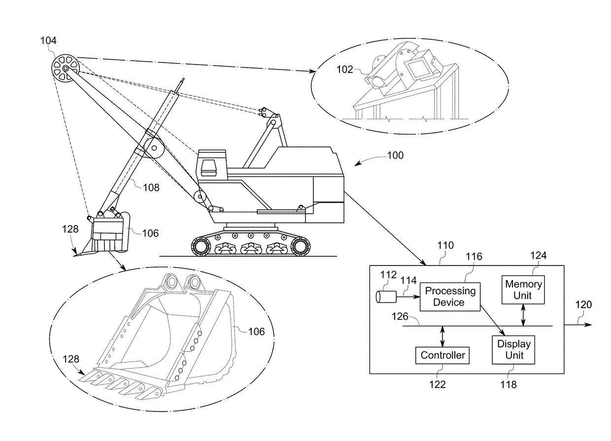
[0014]As will be described in detail hereinafter, systems and methods for detecting an event, where the event may represent absence of at least a portion of a mining equipment. In certain embodiments, the event may represent absence of at least a portion of a tooth of the plurality of teeth of the mining equipment. In one example, the systems and methods are configured to detect a missing tooth in a mining shovel during operation.

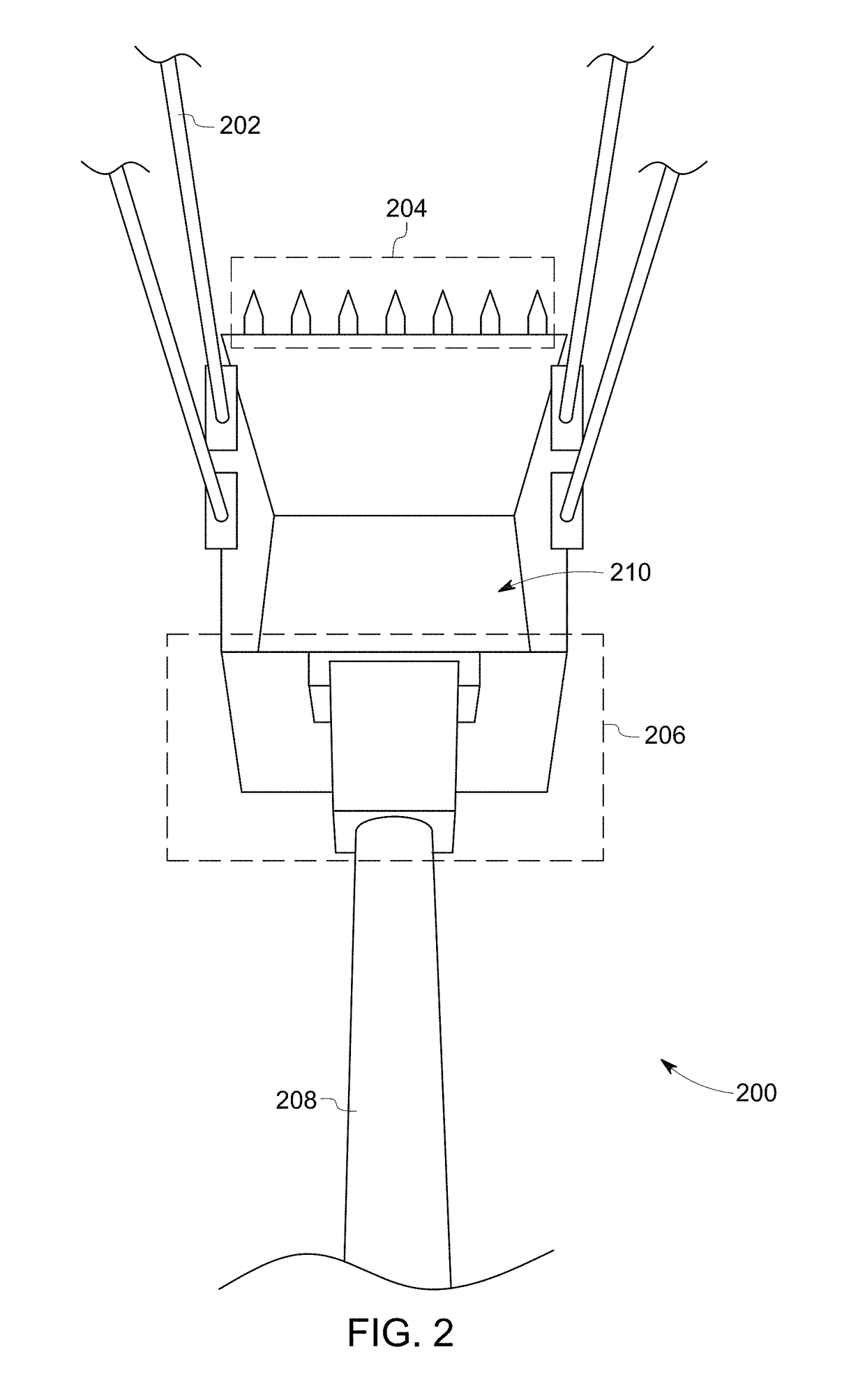
[0015]The term ‘motion range’ refers to a range of distance a shovel bucket is enabled to move by a mining rope. The term ‘template image’ refers to a reference image of a shovel corresponding to a position along the motion range. The term ‘shovel template set’ refers to a set of tuples with each tuple having a plurality of template set elements. In one embodiment, each of the template set element includes, but is not limited to, a template image, a location of the shovel bucket, a location of the tooth line region, a bucket template image, and an image of ...


PUM


Abstract

A method for detecting missing tooth in mining shovel, implemented using a processing device, includes receiving a pair of image frames from a camera disposed on a rope mine shovel configured to carry a mining load. A tooth line region corresponding to the pair of image frames is detected to generate a pair of tooth line regions based on a shovel template set. A difference image is determined based on the pair of image frames and the pair of tooth line regions. Further, a response map representative of possible tooth positions is determined based on the difference image using a tooth template matching technique. A tooth line is selected among a plurality of candidate tooth lines based on the response map. Further, a tooth condition is determined based on the tooth line and the difference image. The tooth condition is notified to an operator of the rope mine shovel.

Description

BACKGROUND[0001]Embodiments of the present specification relate generally to mining industry, and are especially directed towards a vision system for monitoring tooth condition and detecting a missing tooth in a rope mine shovel.[0002]Mineral from a mine is processed by a crusher to obtain particles of uniform size under eight inches in diameter. Crushers are large electric equipment specialized in crushing the mineral rocks. Transport devices discharge the mineral in the top section of these crushers and the crushed mineral is collected in the bottom discharge which is sent to a concentrator to be subjected to a grinding process. An uncrushable element entering into the crusher may cause a mechanical jam that will force the crusher to be stopped, and so all the mineral discharge and crushing process must also be stopped.[0003]When the mineral include ferromagnetic metals, an electromagnet may be used over a conveyor belt that carries the material to be processed. The magnet attract...

Claims


Application Information

Patent Timeline
Patent Type & Authority Applications(United States)
IPC IPC(8): G06T7/00G06T7/40E02F9/26
CPCG06T7/001E02F9/267G06T7/0008G06T2207/10024G06T2207/30164G06T2207/20076G06T7/408E02F9/2808G06T2207/10016G06T7/74G06T7/248G06T7/254G06T7/269G06T7/90
Inventor LIM, SER NAMZHOU, NINGSOARES, JOAO VITOR BALDINI
Owner GE GLOBAL SOURCING LLC
Learn More