
High elongation ridge ventilation sheet for sloping roof and fabricating method therefor

Active Publication Date: 2017-10-05
CAI JIAN
View PDF0 Cites 1 Cited by
  • Summary
  • Abstract
  • Description
  • Claims
  • Application Information

AI Technical Summary

Benefits of technology

The present invention provides a high elongation ridge ventilation sheet for a sloping roof that uses a fully dry construction method. This results in a roof with a better appearance and air circulating with convection. This invention also reduces roof load and saves energy, resulting in a longer life span for the roof. The existing sloping roof construction is transformed to a wholly dry process using the ridge ventilation sheets. This results in better energy saving and extended life span for the roof.

Problems solved by technology

On the other hand, energy issues have engaged governments to request better energy saving effects for buildings.
Mortar construction in the current technology has the following defects: first, the roof is heavily loaded; second, the construction period is long, and construction is costly and time-consuming; third, the life span is short; fourth, the roof is tainted by mortar and difficult to clean; and fifth, repair is costly and difficult in case of leakage due to inability to find the cause.
In the past 5 years, new techniques in the sloping roof construction have been tried but invariably limited to using batten tiles for primary tiles and mortar construction for ridge tiles, which is commonly called semi-dry construction.
The construction method results in an inability of damp air under the roof to discharge via the ridge portion due to the ridge being packed solidly with cement mortar, and thus, causes the batten tiles to decay quickly within a short life time for the roof.
Further, the mortar constructed ridge tiles taint the primary tiles, are apt to loose and fall off, and thus, result in the leakage and economic loss.

Method used


Image

  • High elongation ridge ventilation sheet for sloping roof and fabricating method therefor
  • High elongation ridge ventilation sheet for sloping roof and fabricating method therefor

Examples


Embodiment Construction

[0026]The present invention is illustrated in details in the figures and following embodiment. The embodiment is implemented based on the present invention but is not meant to limit the scope of the present invention.

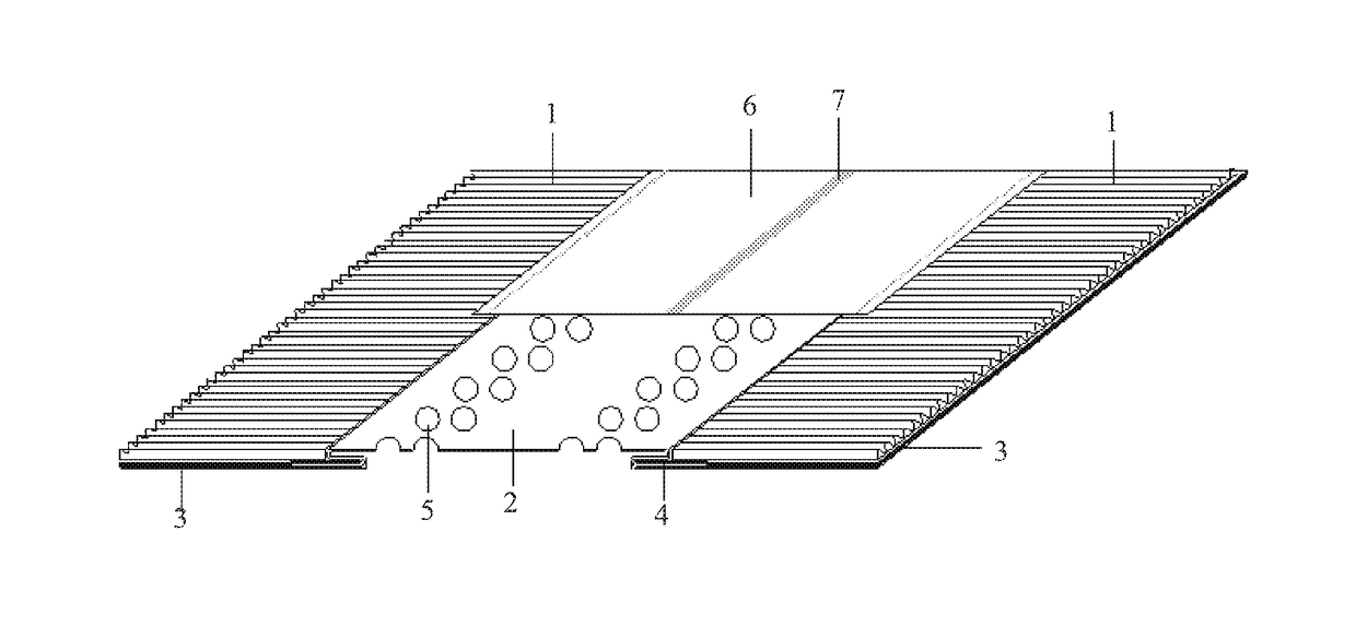
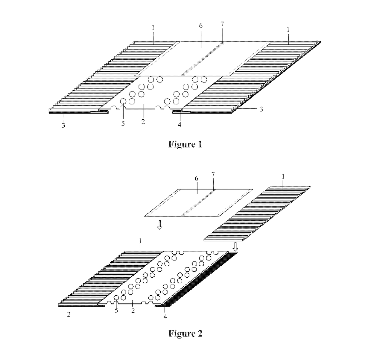
[0027]As shown in FIG. 1, a high elongation ridge ventilation sheet for a sloping roof has a coated composite aluminum membrane 2 with multiple circular holes 5, each side of the coated composite aluminum membrane 2 is bonded with a folded composite aluminum membrane 1 via a butyl adhesive tape for central linking 4 and forms a downward protruding bend. A hot melt adhesive for a polyester nonwoven fabric 6 is arranged on the surface of the polyurethane layer of each folded composite aluminum membrane 1 adjacent the coated composite aluminum membrane 2 for connecting to each folded composite aluminum membrane 1, and the polyester nonwoven fabric 6 covers the whole coated composite aluminum membrane 2. A side butyl adhesive tape 3 having a separator paper is arranged on e...


PUM

PropertyMeasurementUnit
Temperatureaaaaaaaaaa
Elongationaaaaaaaaaa

Abstract

A high elongation ridge ventilation sheet for a sloping roof, having a coated composite aluminum membrane with multiple circular holes, each side of the coated composite aluminum membrane being bonded respectively with a folded composite aluminum membrane via a butyl adhesive tape for central linking, on a side of each folded composite aluminum membrane adjacent the coated composite aluminum membrane is arranged with a hot melt adhesive for connecting a polyester nonwoven fabric with each folded composite aluminum membrane, with the polyester nonwoven fabric covering the whole coated composite aluminum membrane. Further, a fabricating method therefor that realizes wholly dry construction; ridge ventilation sheets adopted on ridge locations not only make the whole roof prettier, but more importantly, enable air convection under the roof in a true sense, taking out extra dampness and heat, resulting in better energy saving effects, and extending life span for the roof.

Description

CROSS-REFERENCE TO RELATED APPLICATIONS[0001]The subject application is a continuation-in-part of PCT / CN2015 / 091154 filed on Sep. 30, 2015 and claims priority on Chinese application no. 201410821560.3 filed on Dec. 22, 2014. The contents and subject matter of the PCT and Chinese priority application are incorporated herein by reference.TECHNICAL FIELD[0002]The present invention relates to roof construction engineering and planted roof engineering, particularly, a high elongation ridge ventilation sheet for a sloping roof and a fabricating method therefor.BACKGROUND OF INVENTION[0003]Improved life standard has called for more attention on quality, functionality, and appearance of buildings. On the other hand, energy issues have engaged governments to request better energy saving effects for buildings.[0004]Mortar construction in the current technology has the following defects: first, the roof is heavily loaded; second, the construction period is long, and construction is costly and ...

Claims


Application Information

Patent Timeline
IPC IPC(8): E04D1/30E04D3/18B32B5/02B32B15/09B32B15/20B32B37/12E04D13/17B32B3/28
CPCE04D1/30E04D13/174E04D3/18B32B3/28B32B2419/06B32B15/20B32B37/12B32B5/022B32B15/09B32B7/12B32B15/14B32B3/26B32B2255/06B32B2255/26B32B2262/0276B32B2307/712Y10T428/19Y10T428/24686Y10T428/24331
Inventor CAI, JIAN
Owner CAI JIAN
Learn More