
Discharging member, and charge eliminating device/image forming apparatus including the discharging member

a technology of discharging member and discharging device, which is applied in the direction of electrographic process apparatus, instruments, optics, etc., can solve the problems of occurrence of memory images and potential decreases on the surface of photosensitive drums

Inactive Publication Date: 2017-09-28
KYOCERA DOCUMENT SOLUTIONS INC
View PDF5 Cites 0 Cited by
  • Summary
  • Abstract
  • Description
  • Claims
  • Application Information

AI Technical Summary

Benefits of technology

The patent describes a method for eliminating residual charge from a photosensitive drum using a noncontact charge elimination method. This method prevents photocarriers from remaining inside the photosensitive layer, reducing the likelihood of decreased surface potential. Additionally, the method prevents flaws and contamination on the surface of the photosensitive drum, resulting in a stable charge elimination effect over a long period.

Problems solved by technology

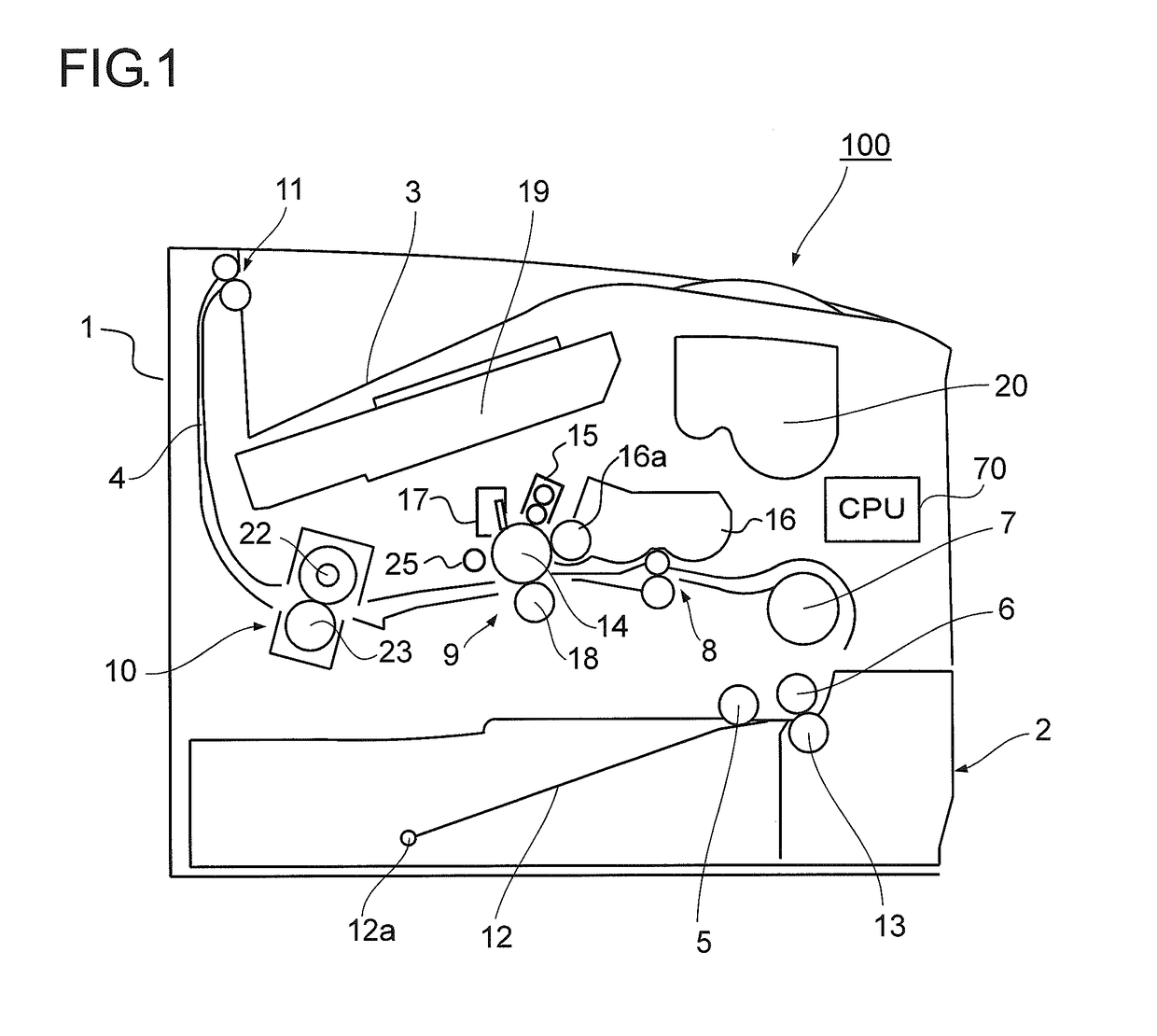
In an image forming apparatus using electrophotographic process, electric charge remaining on a photosensitive drum (image carrier) after transfer of a toner image therefrom may cause occurrence of a memory image due to potential variations in subsequent image formation.
In this case, there arises a fault of potential decreases on the surface of the photosensitive drum caused by photocarriers.

Method used


Image

  • Discharging member, and charge eliminating device/image forming apparatus including the discharging member
  • Discharging member, and charge eliminating device/image forming apparatus including the discharging member
  • Discharging member, and charge eliminating device/image forming apparatus including the discharging member

Examples


example 1

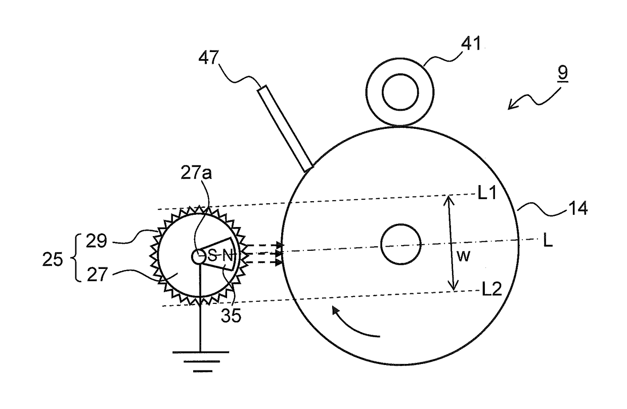
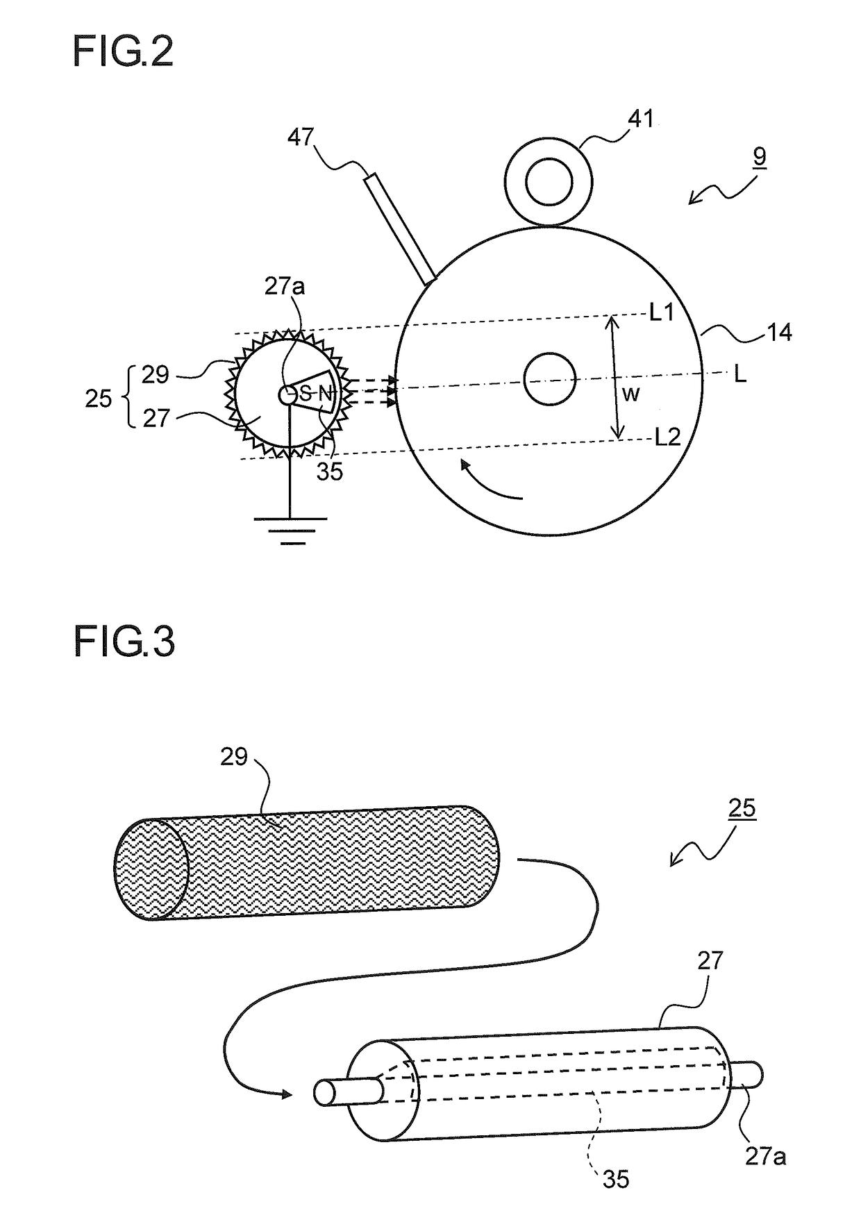
[0065]Charge elimination performance of the charge eliminating roller 25 was evaluated with use of the image forming apparatuses 100 of the first to third embodiments (Disclosures 1 to 5) including the image forming parts 9 as shown in FIG. 2 and FIGS. 6 and 7. With regard to the charge elimination performance, a halftone image at a print coverage rate of 25% was printed out, and it was ascertained whether or not stripes due to any charge elimination fault appeared after elimination of residual charge of the photosensitive drum 14 effected by the charge eliminating roller 25.

[0066]As test conditions, an FS-13200 modified machine (made by KYOCERA Document Solutions Inc.) was used as the image forming apparatus 100, the diameter of the photosensitive drum 14 was set to 30 mm, and the linear velocity was set to 150 mm / sec. As to the charge eliminating roller 25, the diameter of the support member 27 was set to 14 mm, and with regard to Disclosures 1 to 5, the conductive knit fabric 29 ...

example 2

[0070]Charge elimination performance of the charge eliminating roller 25 was evaluated with use of the image forming apparatuses 100 of the fourth to sixth embodiments (Disclosures 6 to 10) including the image forming parts 9 as shown in FIGS. 8 to 10. Further, similar evaluation was performed with use of image forming apparatuses 100 (Comparative Examples 3, 4) including the charge eliminating roller 25 in which woven fabric made from copper fibers was used in place of the conductive knit fabric 29. Test method, test conditions and evaluation criteria were the same as in Example 1, whereas the linear velocity of the photosensitive drum 14 was set to 250 mm / sec, which was faster than in Example 1. Results along with configurations of the charge eliminating roller 25, the charge eliminating roller-side magnet 35, and the drum-side magnet 37 are shown in Table 2.

TABLE 2Charge eliminating rollerMagnet memberFiberChargeDirectionChargedia.ConductiveDrumeliminatingof magneticeliminaTionMa...


PUM


Abstract

A discharging member includes an electrically conductive knit fabric, a support member, and a first magnet member. The conductive knit fabric is knitted into a cylindrical shape with use of yarn formed by twisting together a plurality of metal fibers. The support member is cylindrical shaped and inserted in the conductive knit fabric. The first magnet member is placed inside the support member. With the conductive knit fabric grounded or with a voltage applied to the conductive knit fabric, the discharging member is placed in noncontact with a discharged member in such a fashion that the first magnet member is opposed to the discharged member with the support member and the conductive knit fabric interposed therebetween.

Description

INCORPORATION BY REFERENCE[0001]This application is based upon and claims the benefit of priority from the corresponding Japanese Patent Application No. 2016-56596 filed on Mar. 22, 2016, the entire contents of which are incorporated herein by reference.BACKGROUND[0002]The present disclosure relates to a discharging member for discharging photosensitive members, transfer sheets, fixing members and the like to be used in image forming apparatuses using an electrophotographic system, such as copiers, printers, facsimiles, and multifunction peripherals of their functions. The disclosure also relates to a charge eliminating device as well as an image forming apparatus including the discharging member.[0003]In an image forming apparatus using electrophotographic process, electric charge remaining on a photosensitive drum (image carrier) after transfer of a toner image therefrom may cause occurrence of a memory image due to potential variations in subsequent image formation. Therefore, be...

Claims


Application Information

Patent Timeline
Patent Type & Authority Applications(United States)
IPC IPC(8): G03G21/00
CPCG03G15/0241G03G21/06G03G15/6552
Inventor TAMAKI, KENICHISHIMIZU, TAMOTSUITANI, HIROKA
Owner KYOCERA DOCUMENT SOLUTIONS INC
Learn More