
Internal combustion engine

a combustion engine and combustion chamber technology, applied in the direction of machines/engines, automatic control of ignition, electric control, etc., can solve the problems of unburned hc emissions, difficult to obtain purification performance of catalysts, and likely knocking by delay in cooling water temperature reduction, etc., to achieve the effect of suppressing knocking

Active Publication Date: 2017-09-28
TOYOTA JIDOSHA KK
View PDF18 Cites 8 Cited by
  • Summary
  • Abstract
  • Description
  • Claims
  • Application Information

AI Technical Summary

Benefits of technology

The patent text describes a solution for an internal combustion engine to prevent knocking and manage the temperature of the engine head when switching from a lean mode to a stoichiometric mode. This is achieved by controlling the temperature of the cooling water flowing through the engine head. By doing so, the engine can maintain optimal temperatures for each mode while suppressing knocking. The patent proposes a method for reducing the actual compression ratio, enhancing cooling of the piston and cylinder wall surface, and slowing down combustion. Overall, the patent aims to provide an engine that can efficiently manage cooling to prevent knocking and optimize performance in different operating modes.

Problems solved by technology

However, in a lean mode in which operation is performed at an air-fuel ratio that is leaner in fuel than the theoretical air-fuel ratio, it is required to decrease the amount of unburned HC emitted from the internal combustion engine rather than to suppress knocking.
The reason is that the temperature of exhaust gas does not become high because the combustion temperature in the lean mode is low and thereby the purification performance of a catalyst is hard to be satisfactorily obtained.
Thus, at the time of switching from the lean mode to the stoichiometric mode, knocking is likely to occur by the delay of the reduction in the cooling water temperature.

Method used


Image

  • Internal combustion engine
  • Internal combustion engine
  • Internal combustion engine

Examples


Embodiment Construction

[0026]Embodiments of the present disclosure are described hereunder with reference to the accompanying drawings.

1. Overall Configuration of Internal Combustion Engine

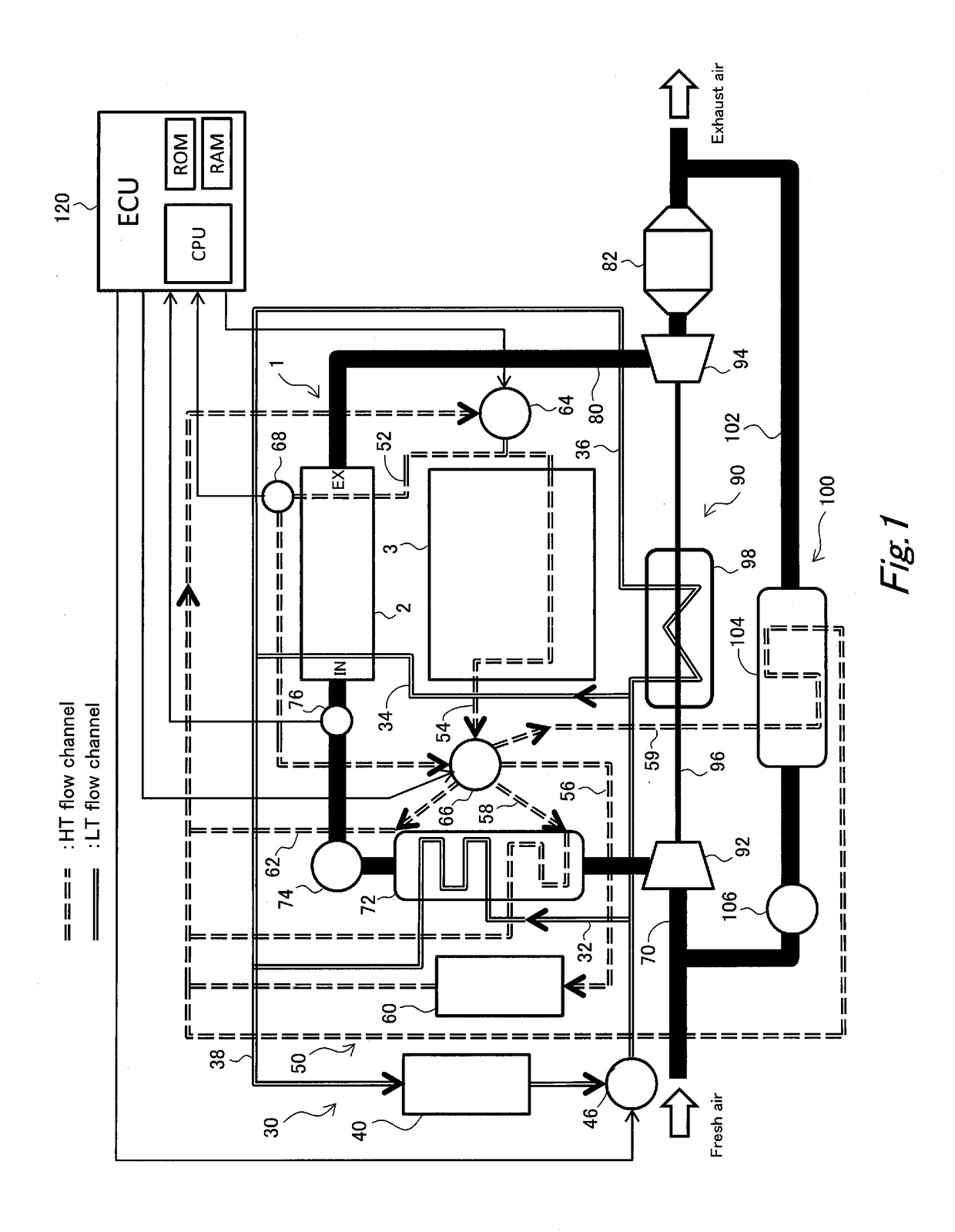
[0027]FIG. 1 is a conceptual diagram illustrating the overall configuration of an internal combustion engine of an embodiment. An internal combustion engine (hereunder, referred to simply as “engine”) 1 includes an engine block 3, and an engine head 2 that is arranged via an unshown gasket on the engine block 3.

[0028]An intake passage 70 and an exhaust passage 80 are connected to the engine head 2. A compressor 92, an intercooler 72 and an electronically controlled throttle 74 are arranged in that order in the intake passage 70 from the upstream side thereof towards the engine head 2. In the intake passage 70 on the downstream side relative to the throttle 74, an intake-air temperature sensor 76 is installed for measuring the temperature of intake air that is introduced into the engine head 2. In the exhaust passage 80,...


PUM


Abstract

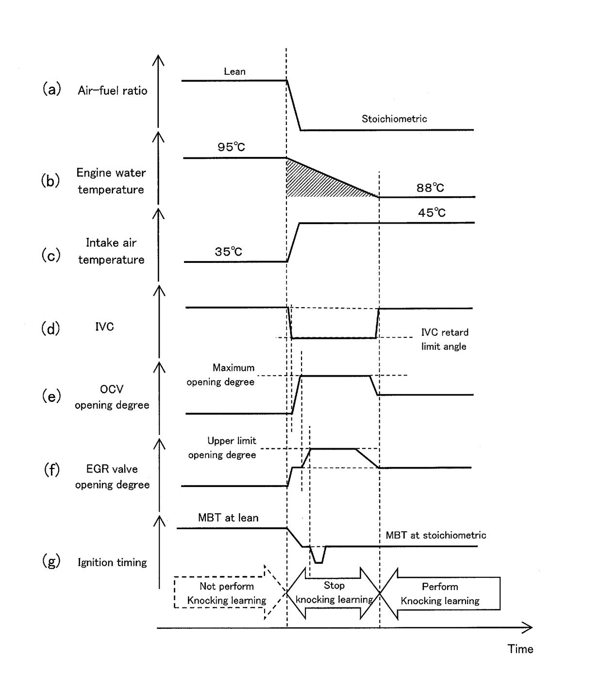
The control apparatus operates an engine water temperature adjustment apparatus so that the temperature of cooling water that passes through an engine head enters a first temperature region in a lean mode, and operates the engine water temperature adjustment apparatus so that the temperature of the cooling water enters a second temperature region that is lower than the first temperature region in a stoichiometric mode. When knocking is detected after switching is started from the stoichiometric mode to the lean mode, the control apparatus performs any one of a first operation to operate a variable valve apparatus so as to retard the closing timing of an intake valve, a second operation to operate an oil jet apparatus so as to increase an oil jet amount, and a third operation to operate an EGR apparatus so as to increase an EGR amount.

Description

CROSS-REFERENCE TO RELATED APPLICATION[0001]This application is based on and claims the benefit of Japanese Patent Application No. 2016-063500, filed on Mar. 28, 2016, which is incorporated by reference herein in its entirety.BACKGROUND[0002]Field of the Disclosure[0003]The present disclosure relates to an internal combustion engine, and more particularly to an internal combustion engine that, in accordance with an operating region, switches between a stoichiometric mode in which the engine performs operation at the theoretical air-fuel ratio, and a lean mode in which the engine performs operation at an air-fuel ratio that is leaner in fuel than the theoretical air-fuel ratio.[0004]Background Art[0005]JP 2003-239747 A discloses a technique to suppress knocking. According to the technique disclosed in JP 2003-239747 A, a knocking index that indicates easiness in the occurrence of knocking in an internal combustion engine is stored in association with operating conditions, and the flo...

Claims


Application Information

Patent Timeline
Patent Type & Authority Applications(United States)
IPC IPC(8): F02D41/14F01P7/16F02F3/22F02D41/00F02P5/04F01P5/10F01P3/02F01L1/344
CPCF02D41/1498F01P3/02F01P7/167F01P7/165F01P2003/024F02D41/0052F02P5/04F01P5/10F02F3/22F01L1/344F01L1/047F01L1/053F01L1/12F01L1/18F01L1/181F01L1/26F01L1/34F01L2001/0476F02P5/152F02D35/027F01L2305/00Y02T10/40
Inventor HOTTA, SHINTAROTANAKA, HIROYUKI
Owner TOYOTA JIDOSHA KK
Learn More