
Compression device

Active Publication Date: 2017-09-28
3M INNOVATIVE PROPERTIES CO
View PDF6 Cites 8 Cited by
  • Summary
  • Abstract
  • Description
  • Claims
  • Application Information

AI Technical Summary

Benefits of technology

The present invention provides a compression system for applying compression to a body part of a user. The system includes a sleeve that is designed to cover a portion of the user's body part. The sleeve has two lateral side edges, and it comprises a central region and two lateral side regions. The central region of the sleeve has a high elasticity in both the transverse and longitudinal directions of the sleeve, with a maximum elongation of 15% under a load of 10 N per cm width. The sleeve also has tension and elongation characteristics in one of its directions, which ensures that when the sleeve is worn, it fits snugly against the user's body part and provides uniform compression. The compression system also includes a releasable closure system that tightens the sleeve around the user's body part. This system provides effective compression therapy while maintaining favorable surface conformability and high static or dynamic stiffness indices.

Problems solved by technology

While the aforementioned other compression systems may be, in part, easier to put on, it has been found that these systems still suffer a number of disadvantages, e.g. not providing desirable therapeutic compressive pressure and / or showing open areas, e.g. between bands or other open spaces (leading to undesirable area(s) of non-compression within a region undergoing compression and thus a unfavorable potential for fluid accumulation in said area(s)) and / or wrinkling.
Moreover, we have observed, although materials with very short stretch characteristics favorably facilitate effective compression therapy, e.g. facilitating the provision of desirably high standing pressures as a result of a high resistance to stretch, such materials, as a result of their high resistance to stretch, typically have issues in terms of surface conformability, which can lead to, among other things, gapping and / or wrinkling of the material and thus non-uniformity of compression.

Method used


Image

  • Compression device
  • Compression device
  • Compression device

Examples


Embodiment Construction

[0039]It is to be understood that the present invention covers all combinations of particular, suitable,

desirable, favorable, advantageous and preferred aspects of the invention described herein.

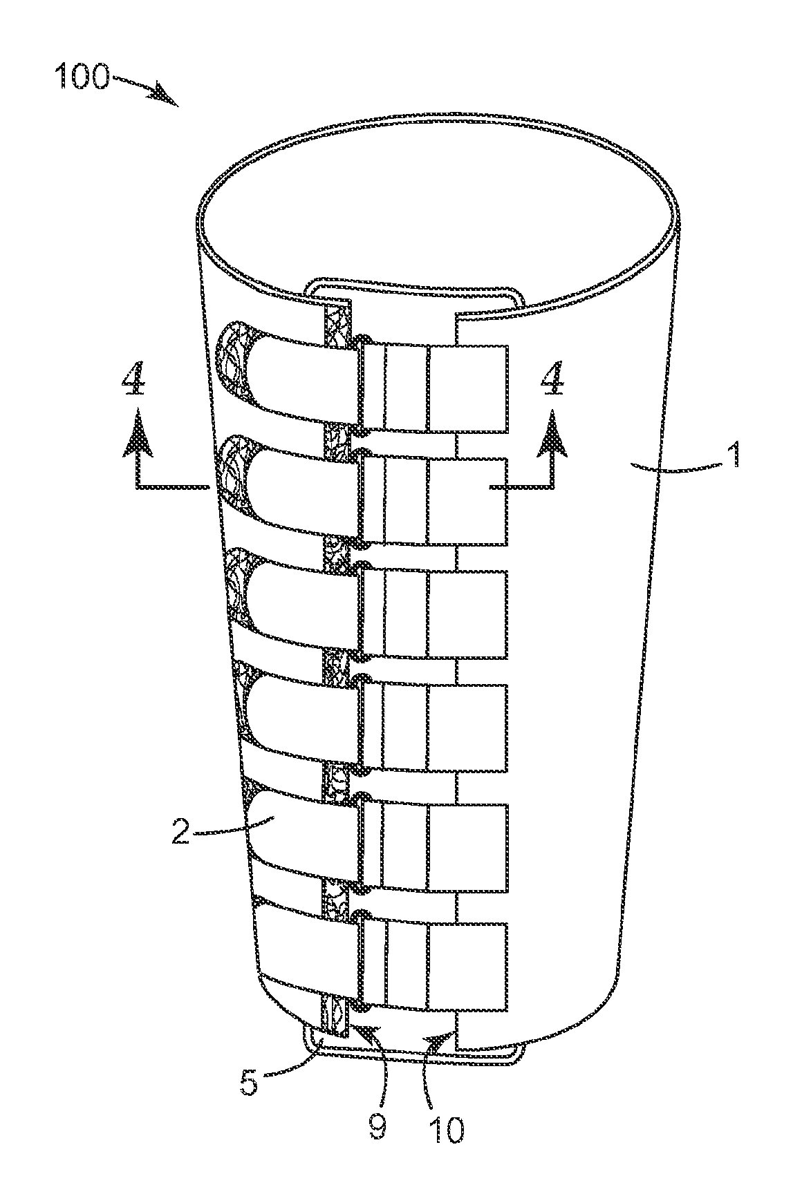
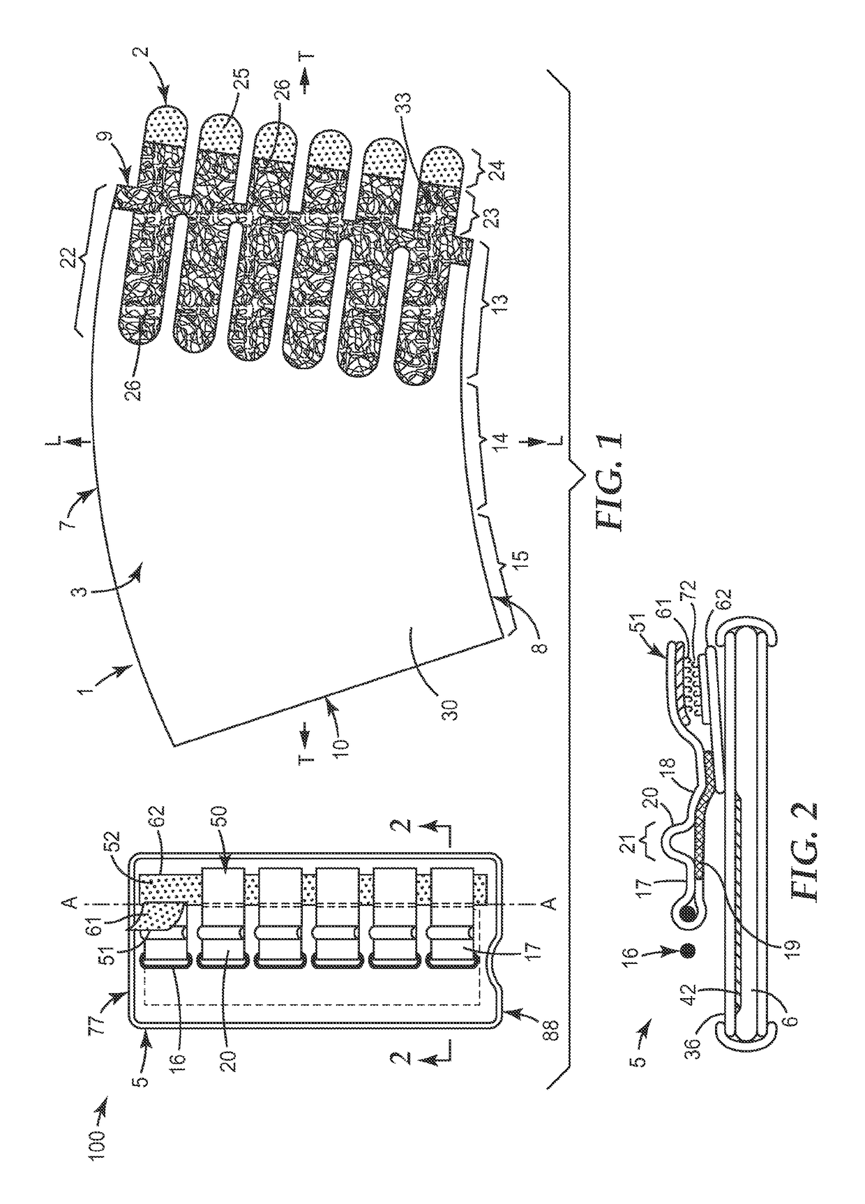
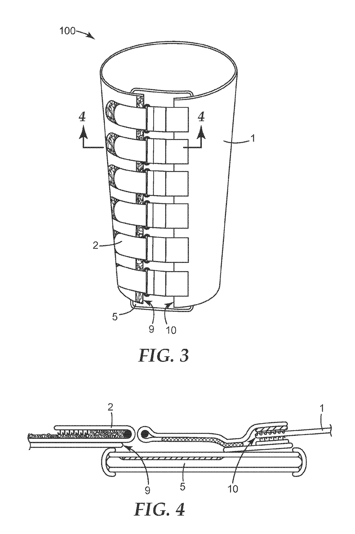
[0040]FIG. 1 shows a top view of the exterior of an exemplary embodiment of a compression system (100) comprising a sleeve (1) for substantially covering a portion of the limb of a user and a secondary closure element (5), while FIG. 2 shows a cross-sectional view of the secondary closure element. As can be appreciated from FIG. 1, sleeves generally include an outer surface (3), an inner surface (4; not numbered on FIG. 1), an upper edge (7) and a lower edge (8). When the device is in use on the limb, typically the inner surface (4) is located towards the wearer / user (in the following the term “inner” will typically refer to something located towards the wearer / user and “outer” away from the wearer / user), while the upper edge is located towards to the torso of the user and the lower edge dis...


PUM


Abstract

A compression system for applying compression to a body part of a user comprising a sleeve for substantially covering a portion of the body part of a user. The sleeve has two lateral side edges. The sleeve comprises a first lateral side region, a central region and a second lateral side region in a transverse direction from the first lateral side edge to the second lateral side edge. At least the central region of the sleeve comprises a material having elasticity in the transverse direction and longitudinal direction of the sleeve, The compression system further comprises a releasable closure system. The closure system is configured and arranged relative to the sleeve, such that, in use, upon closure of the closure system the sleeve is restrained and tightened about the body part of the user.

Description

FIELD[0001]The present invention relates to compression systems, in particular compression systems for applying compression to a body part (e.g. a limb, torso, neck or head) of a user for the use in the treatment and / or management of oedema and other venous and lymphatic disorders, more particularly venous leg ulcers and lymphoedema of a limb.BACKGROUND[0002]Compression therapy is generally prescribed to support an insufficient venous or lymphatic system in returning blood or lymph to the heart. Accordingly compression is generally considered to be the standard treatment for use in the treatment of oedema and other venous and lymphatic disorders e.g. of the lower limbs venous leg ulcers and other clinical conditions, such as lymphoedema. The positive effects of compression therapy on venous lymph return, as well as on the healing of chronic venous (leg) ulcers, are well documented in the medical literature.[0003]Compression bandages are one of the common compression systems used for...

Claims


Application Information

Patent Timeline
IPC IPC(8): A61F13/00A61F13/06A61F13/10
CPCA61F13/00038A61F13/062A61F13/108A61F5/0109A61F2013/15284A61F2013/15292A61F2013/15357A61F13/085A61F13/01038
Inventor HITSCHMANN, GUIDO
Owner 3M INNOVATIVE PROPERTIES CO
Learn More