
Individually identifiable surface acoustic wave sensors, tags and systems

a surface acoustic wave and sensor technology, applied in the direction of baseband system details, impedence networks, electrical apparatus, etc., can solve the problems of limiting the number of sensor codes that will operate simultaneously, preventing the production of larger sets within commercially useful spectral bandwidths, and all prior coded correlation-based systems suffer from difficulties. , to achieve the effect of moderate interference and good autocorrelation properties

Active Publication Date: 2017-09-21
SENSANNA
View PDF6 Cites 0 Cited by
  • Summary
  • Abstract
  • Description
  • Claims
  • Application Information

AI Technical Summary

Benefits of technology

This approach enables the operation of larger sets of sensors with reduced interference, improving sensor identification and measurement accuracy by minimizing code collision effects and enhancing the ability to distinguish between sensor responses, even in asynchronous systems with varying environmental conditions.

Problems solved by technology

A problem with current passive wireless coded SAW sensors and sensor-tags is the limited number of sensor codes that will operate simultaneously due to code collision interactions.
This approach has been used to produce up to 6 resonant sensors, but production of larger sets within commercially useful spectral bandwidths is precluded by bandwidth limitations and the need for guard-banding.
All of the coded correlation-based systems in prior art suffer from difficulty related to the interference between sensor responses due to code cross correlations.
However, in the systems developed to date, the codes used have not been ideal, because sets of DSSS codes that have exactly zero cross-correlation between codes for all relative time alignments simply do not exist.
This makes interpreting the reflected device responses and calibrating the sensor system difficult, and dependent on the precise sensor group choice and sensor spatial distribution.
These limitations apply not just to prior art DSSS wireless sensor systems, but to reflective tapped delay line devices, OFC, and other systems that utilize code diversity in any form, since truly ideal, perfectly non-interacting codes cannot be realized using any of the techniques known to date.

Method used


Image

  • Individually identifiable surface acoustic wave sensors, tags and systems
  • Individually identifiable surface acoustic wave sensors, tags and systems
  • Individually identifiable surface acoustic wave sensors, tags and systems

Examples


barker code example

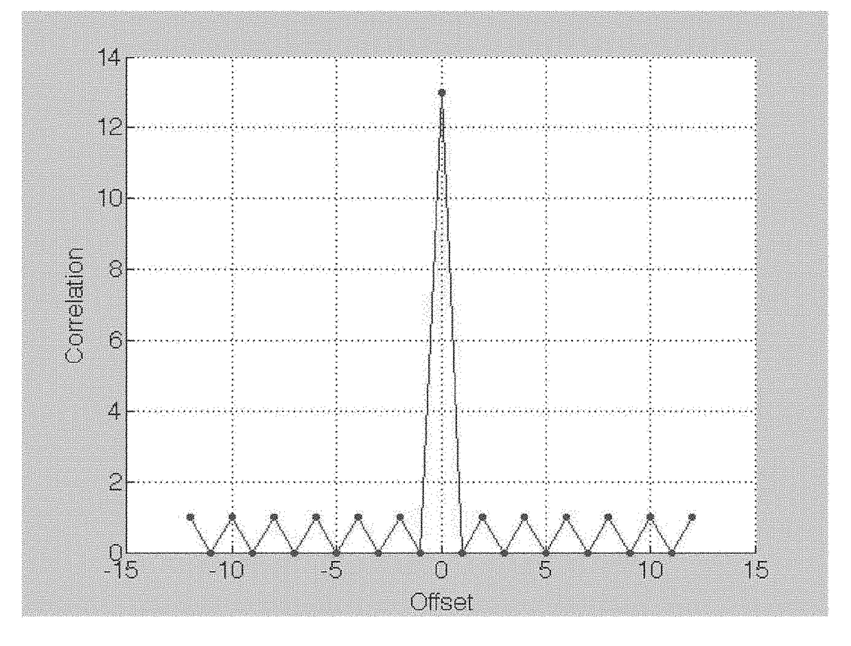
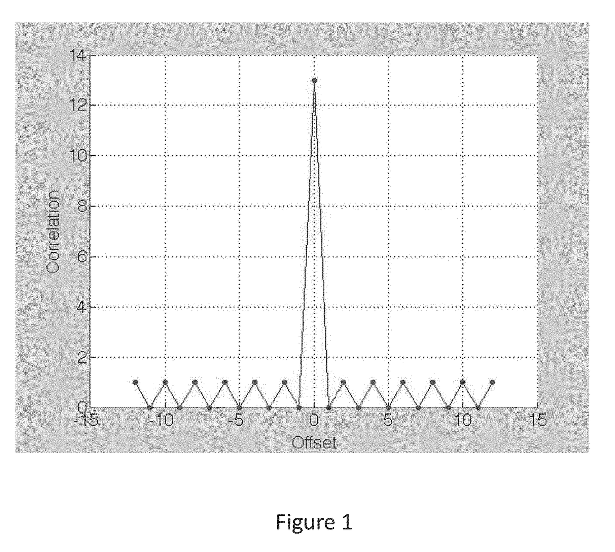
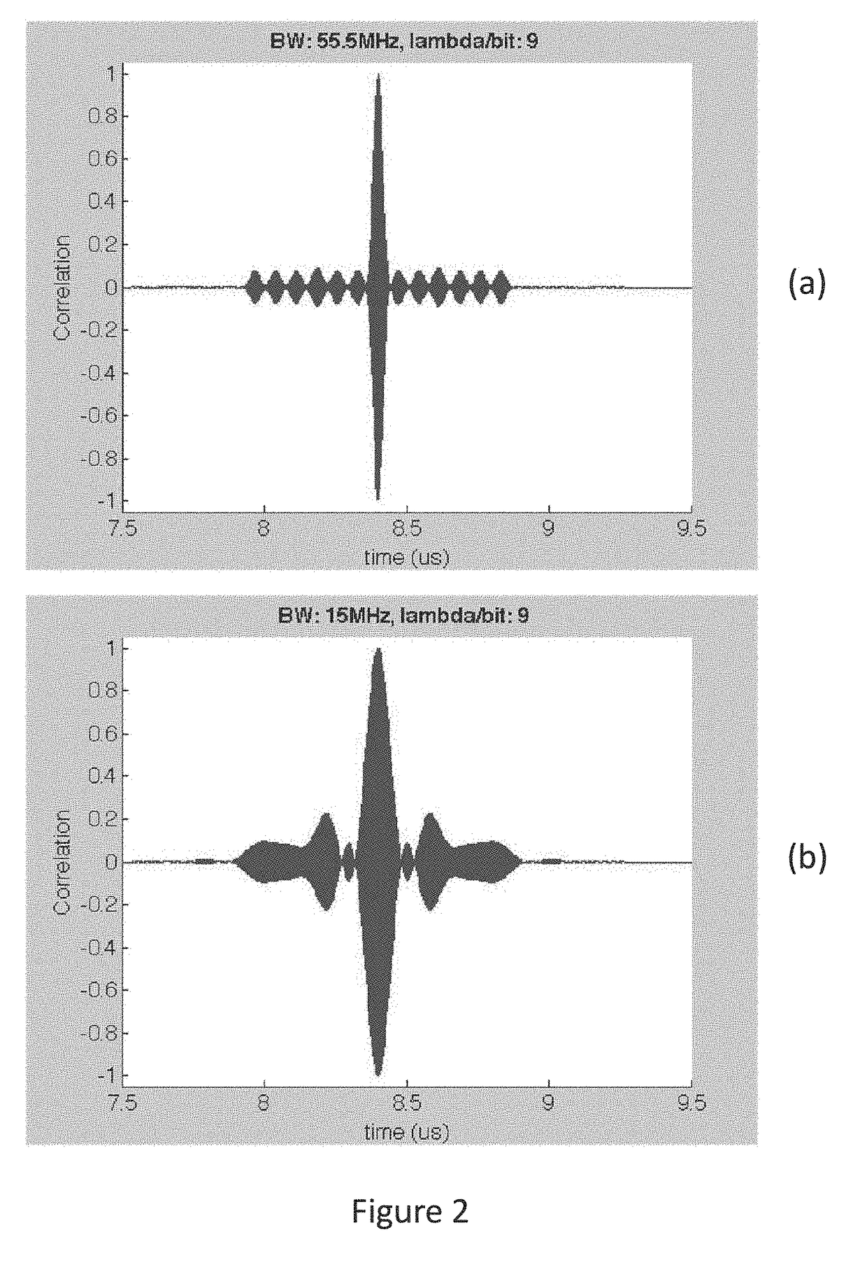
[0067]One example is the 13-bit Barker code. There is only one known Barker code with 13 bits, and it has desirable autocorrelation properties—namely the autocorrelation peak has an amplitude of 13, and the time sidelobes have a magnitude that alternates between 0 and 1, as shown in FIG. 1. Since the sidelobes result from the time-shifted multiplication and integration of the sequence with itself, the behavior exhibited is the best possible behavior attainable with a biphase modulated signal. Implementation of a Barker code in a SAW device, however, is influenced by the characteristics of how the device is built. Consider a simple SAW device with a 13-bit Barker coded input transducer and an uncoded output transducer that functions as a bandpass filter to band-limit the frequency response of the Barker code. The Barker coded transducer will be implemented using bits that are a specific number of acoustic wavelengths long (at the operating center frequency of the device). The longer ...


PUM


Abstract

A surface-launched acoustic wave sensor tag system for remotely sensing and / or providing identification information using sets of surface acoustic wave (SAW) sensor tag devices is characterized by acoustic wave device embodiments that include coding and other diversity techniques to produce groups of sensors that interact minimally, reducing or alleviating code collision problems typical of prior art coded SAW sensors and tags, and specific device embodiments of said coded SAW sensor tags and systems. These sensor / tag devices operate in a system which consists of one or more uniquely identifiable sensor / tag devices and a wireless interrogator. The sensor device incorporates an antenna for receiving incident RF energy and re-radiating the tag identification information and the sensor measured parameter(s). Since there is no power source in or connected to the sensor, it is a passive sensor. The device is wirelessly interrogated by the interrogator.

Description

CROSS-REFERENCE TO RELATED APPLICATIONS[0001]This application claims the benefit of U.S. Provisional Application No. 61 / 586,983, filed Jan. 16, 2012, herein incorporated by reference in its entirety.STATEMENT REGARDING FEDERALLY SPONSORED RESEARCH OR DEVELOPMENT[0002]This invention was made with government support under contract NNX10CD41P awarded by the National Aeronautics and Space Administration (NASA). The government has certain rights in the invention.BACKGROUND OF THE INVENTION[0003]Field of the Invention[0004]Embodiments of the present invention relate to apparatus, systems, devices, and methods for remotely sensing and / or providing identification information using sets of surface acoustic wave (SAW) based sensor tag devices and systems incorporating such devices. In particular, embodiments of the present invention relate to improved methods for implementing coding and other diversity techniques within SAW sensors and tags to produce sets of individually identifiable devices...

Claims


Application Information

Patent Timeline
Patent Type & Authority Applications(United States)
IPC IPC(8): H04L25/02H01L41/08H03H9/25H10N30/00
CPCH04L25/02H03H9/25H01L41/08H03H9/6406H04B1/69H04J13/107H04B2001/6912
Inventor HINES, JACQUELINE H.SOLIE, LELAND P.TUCKER, DANA Y.G.HINES, ANDREW T.
Owner SENSANNA
Learn More