
Drive circuit, angular velocity detection device, electronic apparatus, and moving object

a technology of angular velocity detection and drive circuit, which is applied in the direction of speed measurement using gyroscopic effects, instruments, surveying and navigation, etc., can solve the problems of reduced s/n ratio of voltage signal after conversion, insufficient current amplification, and extremely small current output of sensor elements. , to achieve the effect of reducing the s/n ratio, amplifying the current, and improving the s/n ratio

Inactive Publication Date: 2017-09-07
SEIKO EPSON CORP
View PDF1 Cites 3 Cited by
  • Summary
  • Abstract
  • Description
  • Claims
  • Application Information

AI Technical Summary

Benefits of technology

The invention provides a drive circuit that reduces jitters in the drive signal, an angular velocity detection device that improves accuracy, and an electronic apparatus and moving object that use the angular velocity detection device. The technical effects include reducing jitters in the drive signal, improving accuracy in detecting angular velocity, and enabling high-accuracy processing based on changes in angular velocity.

Problems solved by technology

However, in the angular velocity detection device using the silicon MEMS technology, a current (detection signal) output from the sensor element is extremely small compared to the current output from the sensor element made of crystal disclosed in JP-A-2014-197010.
Therefore, if this extremely small amount of current is received by the I / V conversion circuit disclosed in JP-A-2014-197010, the current cannot be sufficiently amplified and an S / N ratio of the voltage signal after conversion is reduced, and thus, jitters of the drive signal increase.
Then, since a reference signal input to a synchronous detection circuit included in an angular velocity detection circuit is generated based on the drive signal, consequently, an accuracy of detection by the angular velocity detection device deteriorates.

Method used


Image

  • Drive circuit, angular velocity detection device, electronic apparatus, and moving object
  • Drive circuit, angular velocity detection device, electronic apparatus, and moving object
  • Drive circuit, angular velocity detection device, electronic apparatus, and moving object

Examples


modification examples

2-2. Other Modification Examples

[0129]In the embodiment described above, the phase shift circuit 23A may be provided at the stage subsequent to the band limiting filter 24A. Similarly, the phase shift circuit 23B may be provided at the stage subsequent to the band limiting filter 24B. In addition, in the embodiment described above, the comparator 25 may not be provided between the phase adjustment portions 27A and 27B and the level conversion circuit 26, or may be configured such that the output signals from the phase adjustment portions 27A and 27B are directly input to the level conversion circuit 26.

3. Electronic Apparatuses

[0130]FIG. 12 is a functional block diagram of an electronic apparatus 500 in the embodiment. The same reference signs will be given to the similar configuration elements in each embodiment described above, and the descriptions thereof will be omitted.

[0131]The electronic apparatus 500 in the embodiment is an electronic apparatus 500 including the angular velo...


PUM


Abstract

A drive circuit includes a first converter that includes a first operational amplifier and a first capacitance, accumulates first signals output from a first electrode of an angular velocity detection element and input to the first operational amplifier in the first capacitance, and then, converts the signals to a voltage, a first phase adjustment portion that adjusts a phase of the drive signal which drives the angular velocity detection element and limits a frequency band of the drive signal based on the output signals from the first converter, and a drive signal generation portion that generates the drive signal based on the output signals from the first phase adjustment portion.

Description

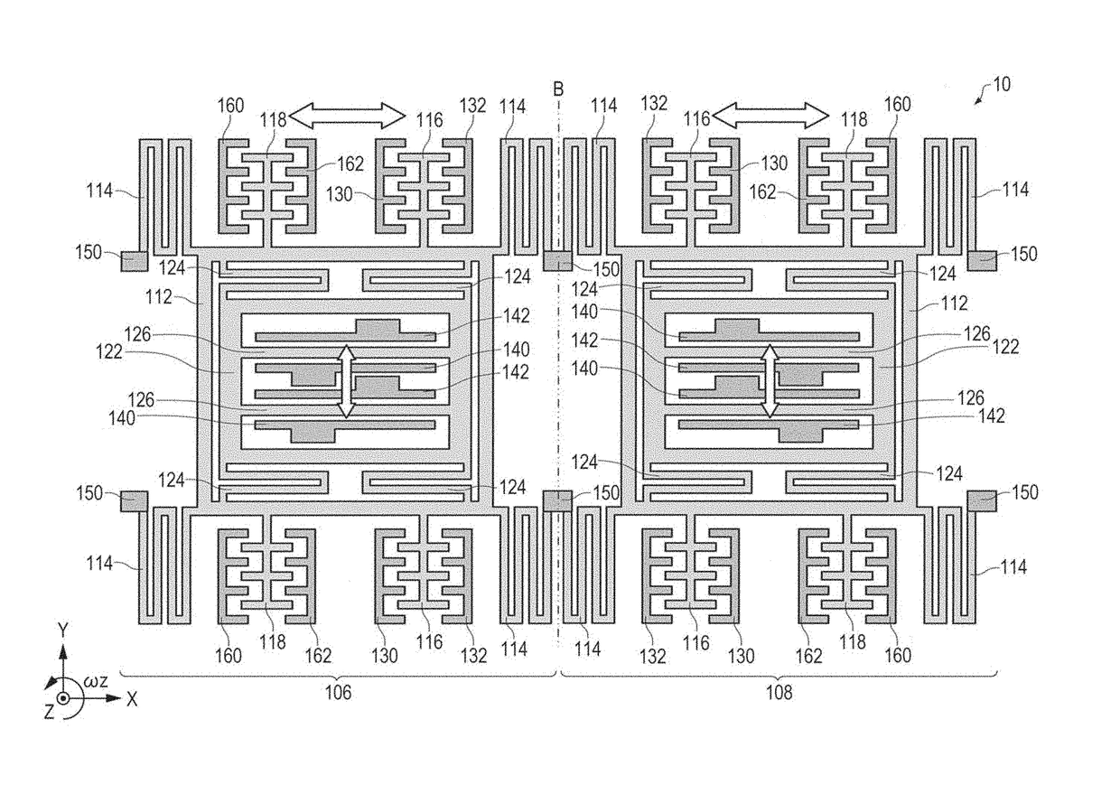
BACKGROUND[0001]1. Technical Field[0002]The present invention relates to a drive circuit, an angular velocity detection device, an electronic apparatus, and a moving object.[0003]2. Related Art[0004]Various electronic apparatuses and systems are widely used, on which an angular velocity detection device (a Gyro sensor) is mounted and which perform predetermined controls based on a detected angular velocity. In JP-A-2014-197010, an angular velocity detection device is disclosed which includes a drive circuit that converts a current output from a sensor element made of quartz crystal to a voltage signal using an I / V conversion circuit and adjusts amplitude of a drive signal which drives the sensor element such that the amplitude of the voltage signal becomes constant.[0005]Incidentally, recent years, an angular velocity detection device that detects the angular velocity using a silicon micro-electromechanical system (MEMS) technology has been developed. The angular velocity detection ...

Claims


Application Information

Patent Timeline
Patent Type & Authority Applications(United States)
IPC IPC(8): G01C19/5726G01C19/5747
CPCG01C19/5747G01C19/5726
Inventor KANEMOTO, KEI
Owner SEIKO EPSON CORP
Learn More