
System, Method, and Apparatus for Improving Safety of ECP-Equipped Trains with Flammable Cargo

a technology of ecp and flammable cargo, applied in failsafe aspects, program control, instruments, etc., can solve the problems of increasing the dangers and costs of a train derailment, catastrophic ignition, and flammable cargo can leak or escape,

Active Publication Date: 2017-09-07
WESTINGHOUSE AIR BRAKE TECH CORP
View PDF13 Cites 8 Cited by
  • Summary
  • Abstract
  • Description
  • Claims
  • Application Information

AI Technical Summary

Benefits of technology

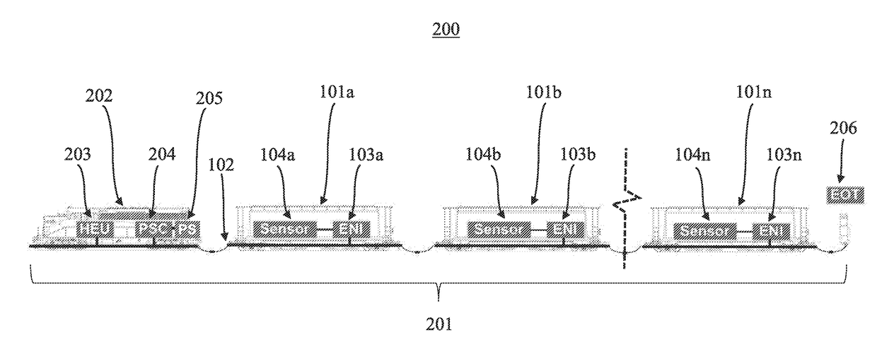
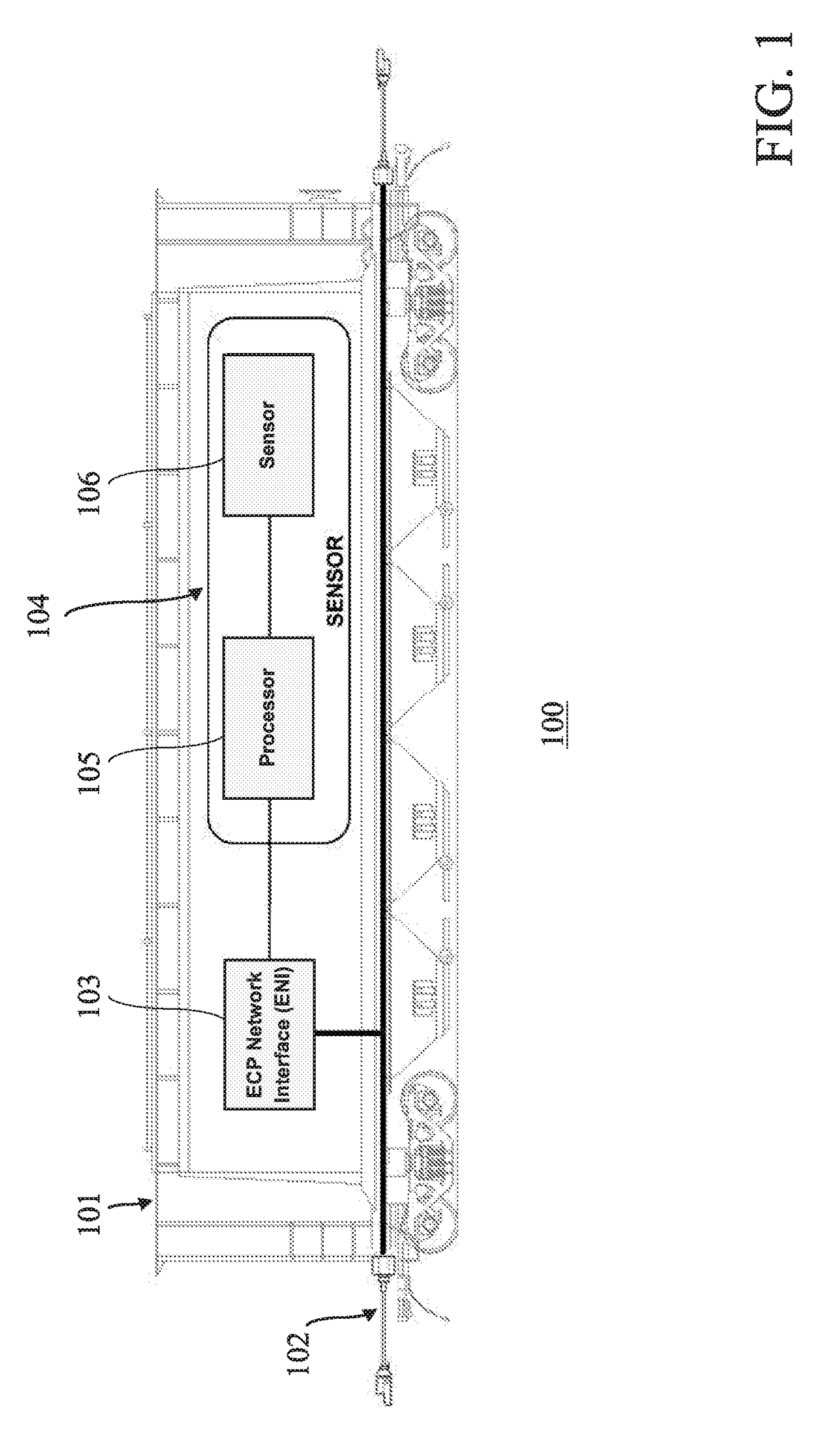
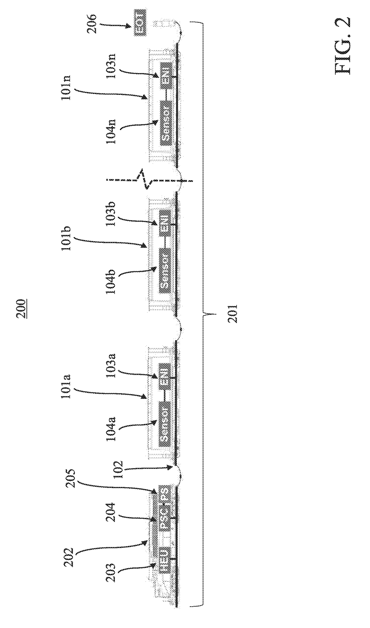
The patent describes a system for monitoring and responding to derailments of railcars carrying flammable cargo. The system includes sensors and a network interface to monitor various conditions or parameters of the railcar, such as vibration, flexion, compression, angular velocity, tilt, external temperature, and internal temperature. The system also includes a local controller that receives and analyzes the railcar data, and a power supply controller that deactivates the power supply in response to potential or actual derailment. The system can help prevent accidents and minimize damage to the train and its occupants.

Problems solved by technology

One known problem with ECP brake systems pertains to its deployment on trains with flammable cargo.
If a train derails, the flammable cargo can leak or escape, which may be ignited by an ignition source, such as an open flame, spark, or exposed electrical current.
The resulting fire or explosion greatly increases the dangers and costs associated with a train derailment.
If the ECP-equipped trainline power supply is transmitting electricity along the trainline during a derailment, and if the power transmission system and cargo-holding railcars are compromised in the derailment, the ECP-equipped trainline power supply could cause a catastrophic ignition.

Method used


Image

  • System, Method, and Apparatus for Improving Safety of ECP-Equipped Trains with Flammable Cargo
  • System, Method, and Apparatus for Improving Safety of ECP-Equipped Trains with Flammable Cargo
  • System, Method, and Apparatus for Improving Safety of ECP-Equipped Trains with Flammable Cargo

Examples


Embodiment Construction

[0055]For purposes of the description hereinafter, the terms “upper”, “lower”, “right”, “left”, “vertical”, “horizontal”, “top”, “bottom”, “lateral”, “longitudinal” and derivatives thereof shall relate to the invention as it is oriented in the drawing figures. However, it is to be understood that the invention may assume various alternative variations and step sequences, except where expressly specified to the contrary. It is also to be understood that the specific devices and process illustrated in the attached drawings, and described in the following specification, are simply exemplary embodiments of the invention. Hence, specific dimensions and other physical characteristics related to the embodiments disclosed herein are not to be considered as limiting.

[0056]As used herein, the terms “communication” and “communicate” refer to the receipt, transmission, or transfer of one or more signals, messages, commands, or other type of data. For one unit or device to be in communication wi...


PUM


Abstract

A safety system for a train equipped with an ECP air brake arrangement, in which the train includes at least one locomotive and at least one railcar connected to a trainline network, the system including: at least one power supply; at least one power supply controller to communicate over the trainline network and control the at least one power supply; at least one local controller to: communicate over the trainline network; receive or determine railcar data including a condition or parameter associated with the at least one railcar; and, based at least partially on the railcar data, generate at least one first message to deactivate the at least one power supply. A computer-implemented method for monitoring and responding to at least one railcar's derailment is also disclosed.

Description

BACKGROUND OF THE INVENTION[0001]Field of the Invention[0002]The present invention is generally related to vehicle systems and networks, such as railway systems including trains travelling in a track or rail network, and more particularly, to a system, method, and apparatus for providing improved safety of trains carrying flammable cargo, including trains that are equipped with electronically-controlled pneumatic (ECP) brake arrangements.[0003]Description of Related Art[0004]Vehicle systems and networks exist throughout the world, and, at any point in time, a multitude of vehicles, such as cars, trucks, buses, trains and the like, are travelling throughout the system and network. With specific reference to trains travelling in a track network, the locomotives of such trains are typically equipped with or operated using train control, communication, and management systems (e.g., positive train control (PTC) systems), such as the I-ETMS® of Wabtec Corp. Such train control systems norm...

Claims


Application Information

Patent Timeline
IPC IPC(8): B60T17/18B60T7/12G05B19/042B61L27/04H04L29/08
CPCB60T17/18B61L27/04H04L67/12B60T2270/40B60T7/124B61L2201/00G05B2219/41279G05B19/0428B61L15/0081B60T13/665B61L15/0072B60T17/228B61L15/0036B61L15/0054
Inventor NAYLOR, MICHAEL A.GANGEMELLA, DONALD W.KLEMANSKI, RICHARD S.HAAS, CARL L.
Owner WESTINGHOUSE AIR BRAKE TECH CORP
Learn More