
An aerial camera system

a camera system and camera technology, applied in the field of aerial camera systems, can solve the problems of affecting the accuracy of photogrammetric solutions, the ratio of distance, and the decrease of the cost per unit area

Inactive Publication Date: 2017-08-24
SPOOKFISH INNOVATIONS
View PDF0 Cites 17 Cited by
  • Summary
  • Abstract
  • Description
  • Claims
  • Application Information

AI Technical Summary

Benefits of technology

The patent describes a system that allows a camera to move its field of view by rotating a steering mirror. The system also synchronizes the movement of the steering mirror with the capture of images to reduce blurring. The technical effect is smoother and more stable camera movement during image capturing.

Problems solved by technology

In order to produce a good photogrammetric solution, a redundancy of about 10 is generally required, but with a relatively long associated focal length for each image and relatively large image overlaps, the ratio of distance between camera locations at image capture and distance to target (the ‘base-to-height’ ratio) is relatively small, which affects accuracy of the photogrammetric solution.
Therefore, since flying costs are primarily determined on an hourly rate, if a system captures more ground area per hour, then the cost per unit area decreases.
However, flying a survey aircraft faster causes motion blur at higher speeds.
Therefore, if it is desired to capture imagery at a resolution of 7.5 cm, the survey aircraft cannot travel any faster than 75 m / s if blur is to be maintained at an acceptable level.
Flying higher causes a greater area of ground to be covered, although increasing the area of ground covered whilst maintaining the same field of view causes the resolution to degrade unless longer focal length lenses or a higher resolution sensor are used.
While longer focal length lenses maintain resolution, the FoV is narrower, which negates the increase in altitude.
Higher resolution sensors are limited by available technology, and image quality typically degrades as the sensor resolution increases because the light collecting area is smaller.
Higher resolution sensors are also typically more expensive.

Method used


Image

  • An aerial camera system
  • An aerial camera system
  • An aerial camera system

Examples


Embodiment Construction

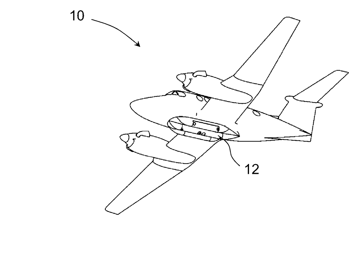
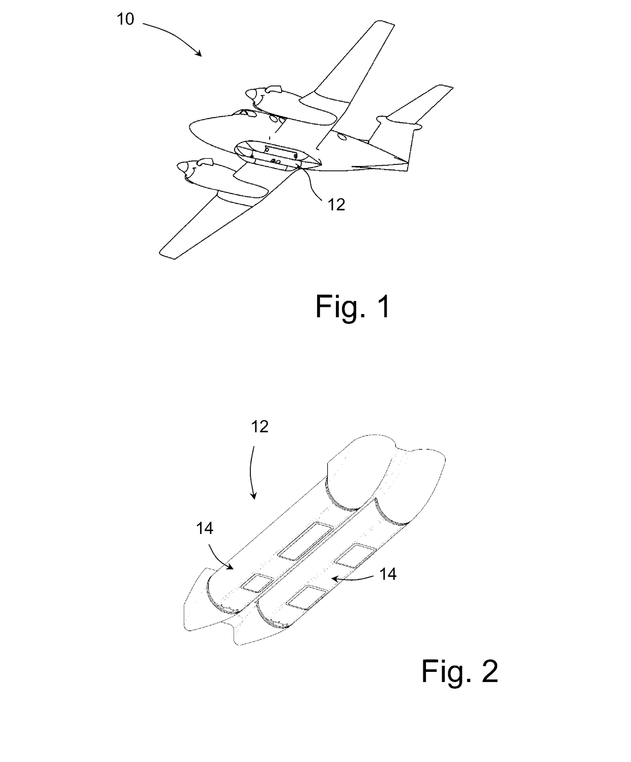
[0100]Referring to FIG. 1 of the drawings, a survey aircraft 10 with mounted aerial camera system 12 is shown.

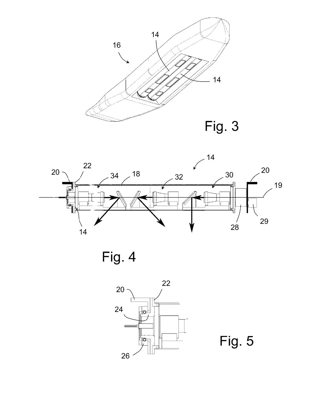
[0101]The aerial camera system 12 includes at least one camera tube assembly 14 arranged to rotate about a respective central longitudinal axis. The camera tube assemblies 14 may be packaged in any suitable way, as shown in FIGS. 2 and 3. FIG. 2 shows a pair of adjacently disposed camera tube assemblies 14, and FIG. 3 shows a cargo pod assembly 16 that includes two camera tube assemblies 14.

[0102]Referring to FIG. 4, a cross-sectional view of a camera tube assembly 14 is shown. FIG. 5 shows an enlarged view of an end portion of the camera tube assembly 14.

[0103]In this example, the camera tube assembly 14 includes a camera tube 18 arranged to rotate about a central longitudinal axis 19, in this example relative to an axle bulkhead 20 mounted relative to the survey aircraft 10.

[0104]The camera tube 18 is connected to a ring frame 22 and the ring frame 22 is fixed to an axle 2...


PUM


Abstract

An aerial camera system is disclosed that comprises at least one camera arranged to capture a plurality of successive images. Each camera including at least one respective image sensor, and the field of view of each camera is movable in a substantially transverse direction across a region of the ground. The system also includes a stabilisation assembly associated with each camera that has at least one steering mirror. The steering mirror is controllably movable so as to translate the optical axis of the camera relative to the at least one image sensor in synchronization with image capture, so as to effect stabilisation of an image on the at least one image sensor during image capture as the field of view of the camera moves in a substantially transverse direction across a region of the ground. The system is arranged to control the at least one camera to capture successive images at defined intervals as the field of view of the camera moves in a substantially transverse direction across a region of the ground.

Description

FIELD OF THE INVENTION[0001]The present invention relates to an aerial camera system for capturing ground images from a survey aircraft.BACKGROUND OF THE INVENTION[0002]It is known to provide an aerial camera system that is arranged to capture ground images from a survey aircraft. Typically, the aerial camera system is mounted to an underside portion of the survey aircraft and ground images are captured as the survey aircraft moves along defined flight lines. The system is arranged to capture multiple images for each ground feature, which enables a photogrammetric solution, such as a bundle adjustment process, to be applied to the captured images in order to determine a best case solution for interior and exterior orientation information associated with each camera used and the images captured by each camera. The solution produced by the bundle adjustment process may then be used to produce nadir and / or oblique photomaps.[0003]In order to improve the photogrammetric solution produce...

Claims


Application Information

Patent Timeline
IPC IPC(8): H04N5/232G01C11/02G03B17/17B64D47/08H04N7/18G03B15/00
CPCH04N5/2328H04N5/23296H04N7/181H04N5/23251G03B2205/0007G03B17/17B64D47/08G01C11/02G03B15/006H04N23/685H04N23/69H04N23/681
Inventor COPE, SIMONVON BERTOUCH, MICHAEL
Owner SPOOKFISH INNOVATIONS
Learn More