
Autonomous Mobile Device and Wireless Charging System Thereof

a mobile device and wireless charging technology, applied in the field of robots, can solve the problems of poor contact, accidental harm to children, and inability to grow vegetables at a place covered by the charging station on the lawn, and achieve the effect of effectively filtering out electromagnetic signals and preventing a magnetic leakage phenomenon

Active Publication Date: 2018-12-27
POSITEC POWER TOOLS (SUZHOU) CO LTD
View PDF7 Cites 14 Cited by
  • Summary
  • Abstract
  • Description
  • Claims
  • Application Information

AI Technical Summary

Benefits of technology

The patent text describes a wireless charging device that can charge a device without needing to connect the two devices. This is done through a signal transfer apparatus that allows for a charging effect to occur when the device is close to the charging device. This eliminates the need to align the two devices perfectly, making the charging process easier. Additionally, the patent describes a feature that can reduce the speed of an autonomous moving device when it is close to another object, to avoid collisions and ensure safety.

Problems solved by technology

However, a wired charging manner is universally used for an autonomous lawn mower and requires a wired charging station to be constructed on a lawn, causing vegetation to be impossible to grow at a place covered by the charging station on the lawn.
The wired charging station generally forms a hump relative to the ground, and a pole piece has a sharp shape, easy to trip over the elderly and cause the children to be accidentally harmed.
Subsequently, it is easy for the pole piece to be eroded and oxidized, causing poor contact, and a problem often occurs during wired charging.
In addition, it is easy for the exposure of the pole piece to cause electricity leakage.
Usually, when the receiving end and the transmitting end correspond to charge, it is difficult for the receiving end and the transmitting end to be fully aligned.
Therefore, the receiving end and the transmitting end cannot be optimally charged.
However, this charging manner is obviously inapplicable to a large machinery device, that is, the autonomous lawn mower.
Based on this, it is necessary to provide a wireless docking and charging method and a system for a lawn mower for a problem of “when the lawn mower in the prior art returns to a charging station for charging, alignment of a charging receiving end of the lawn mower with a power supplying transmitting end of a charging station is problematic, and that the alignment cannot be implemented in time often occurs, causing the lawn mower to be unable to be charged in time, and affecting the next use”.
It is prevented that the lawn mower moves beyond the power supplying transmitting end or a driving path of the lawn mower deviates, causing that docking and charging fails.
It is effectively prevented that the lawn mower moves beyond the power supplying transmitting end or a driving path of the lawn mower deviates, causing that docking and charging fails.
The control board further limit a time period from a time of detecting of the first electrical signal to a time of receiving of the second electrical signal, preventing that energy received by the charging receiving end is effective while it is difficult to satisfy a docking requirement due to a deviation of a docking path.

Method used


Image

  • Autonomous Mobile Device and Wireless Charging System Thereof
  • Autonomous Mobile Device and Wireless Charging System Thereof
  • Autonomous Mobile Device and Wireless Charging System Thereof

Examples


Embodiment Construction

[0176]To make the objectives, technical solutions, and advantages of the present invention clearer, the following further describes the present invention in detail with reference to the accompanying drawings and embodiments. It should be understood that, the specific embodiments described herein are merely used to explain the present invention, and are not intended to limit the present invention.

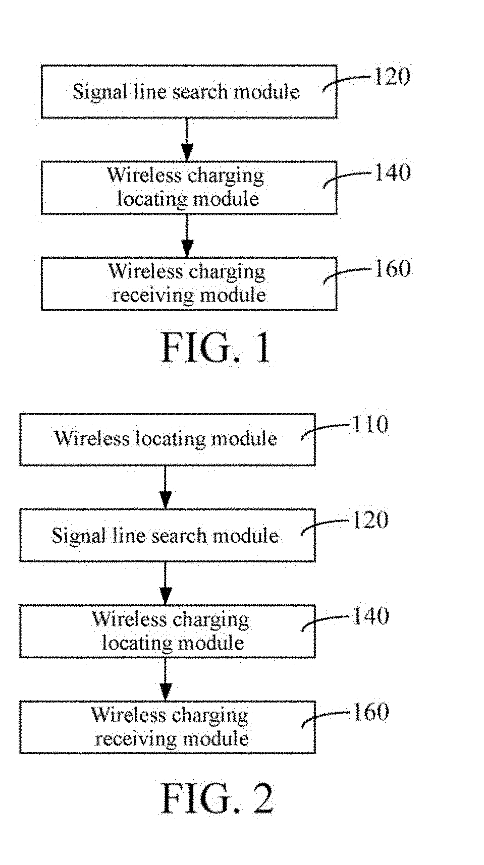
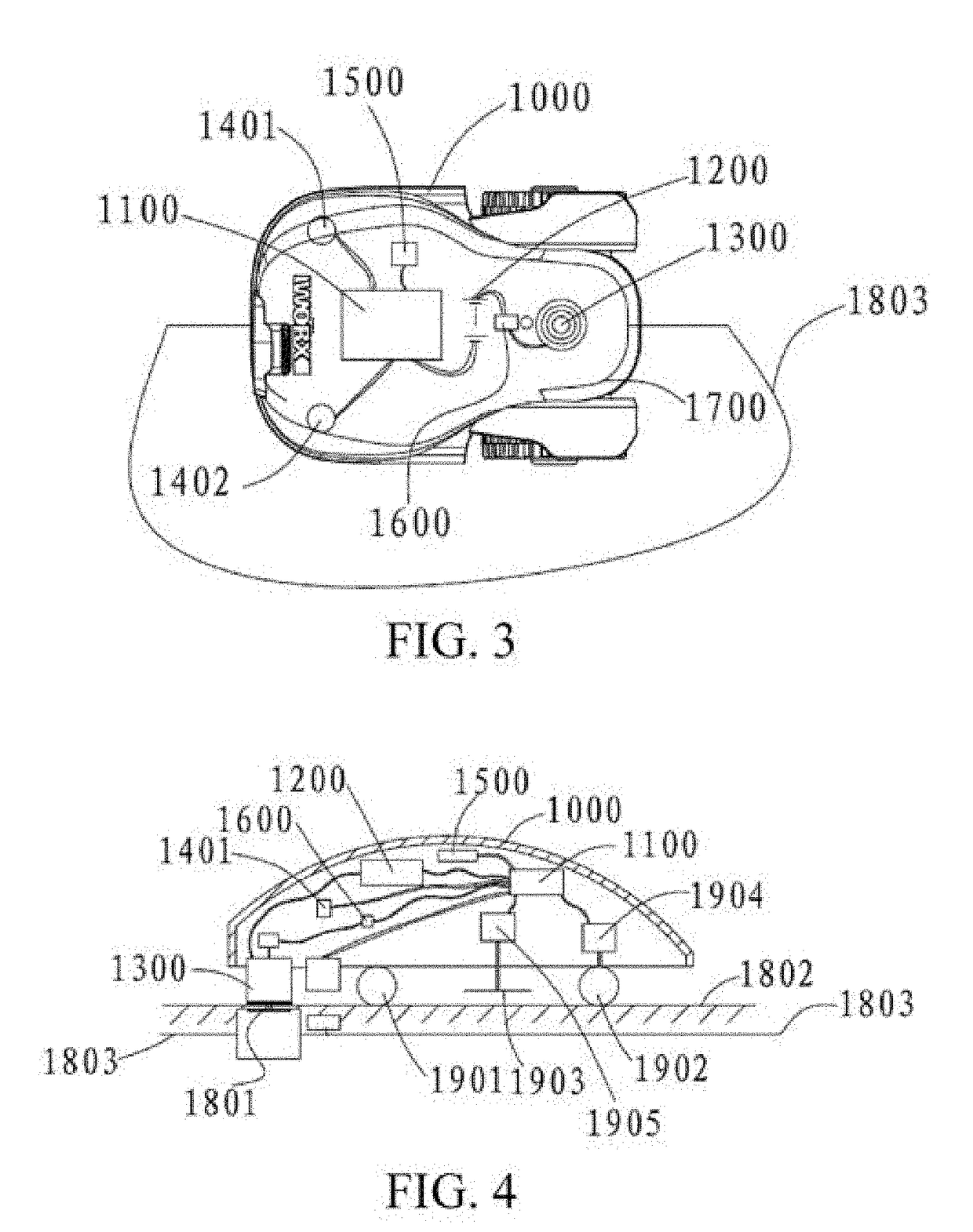
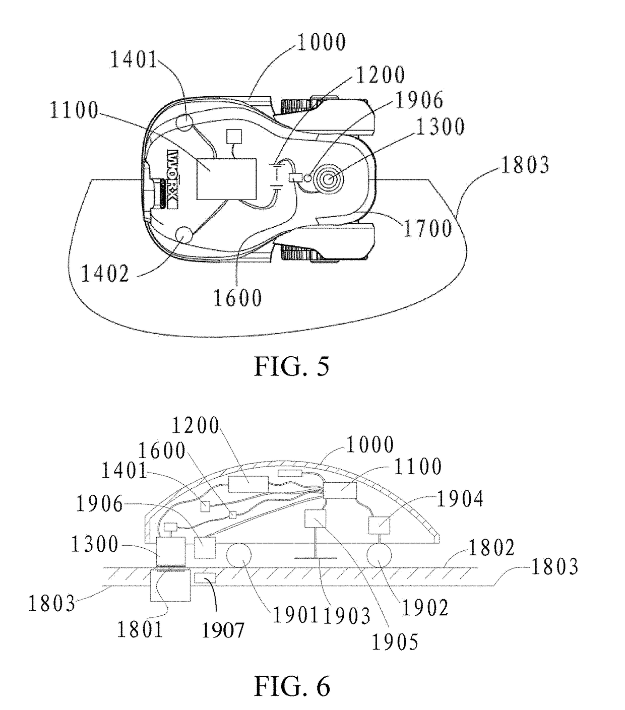
[0177]An robotic moving device, or referred to as an autonomous moving device, or an automatic self-propelling device, generally needs to move within an activity area. The activity area designates a range that the autonomous moving device may move, and correspondingly a wireless charging station that charges the autonomous moving device may be disposed in the activity area. The wireless charging station generally includes a wireless charging transmitting end. In this embodiment, a directing line along which the wireless charging station is located may be further disposed on the wireless char...


PUM


Abstract

An autonomous moving device wireless charging system, including an autonomous moving device and a wireless charging station, the wireless charging station includes a wireless charging transmitting end; the autonomous moving device includes: a wireless charging receiving end, the wireless charging transmitting end wirelessly transmits a charging signal to the wireless charging receiving end to transmit electric energy; a charging battery, electrically connected to the wireless charging receiving end, to receive the electric energy transmitted from the wireless charging receiving end; a wireless charging locating module, the wireless charging locating module determines whether the autonomous moving device is at a charging location; a driving module; and a control module, connected to the wireless charging locating module and driving module, when the wireless charging locating module determines that the autonomous moving device is at the charging location, controlling the driving module, to make the autonomous moving device dock at the charging location.

Description

BACKGROUNDTechnical Field[0001]The present invention relates to the field of robots, and in particular, to an autonomous mobile device and a wireless charging system thereof.Related Art[0002]As intelligentization develops quicker, a lawn mower is autonomously operated instead of being manually operated. Therefore, not only can people mow grass at an obviously higher speed, but also a great convenience is brought. In addition, the application range of wireless charging technology becomes wider. In particular, the technology is applied to various intelligent devices, such as mobile phones. Complex interface connections are reduced by using wireless charging, so that the charging is easier, and the user experience is improved.[0003]However, a wired charging manner is universally used for an autonomous lawn mower and requires a wired charging station to be constructed on a lawn, causing vegetation to be impossible to grow at a place covered by the charging station on the lawn. The wired...

Claims


Application Information

Patent Timeline
IPC IPC(8): B60L11/18G05D1/02H02J7/02H02J7/04
CPCB60L11/1829G05D1/0278H02J7/025H02J7/045G05D1/0225A01D34/008H02J50/10H02J50/90B60L53/38B60L2260/32B60L53/36B60L53/126B60L53/62Y02T10/70Y02T10/7072Y02T90/14Y02T90/12B60L53/12A47L2201/02A47L9/2873H02J7/0013
Inventor LIU, FANGSHISUN, GENDONG, YONGMINGZHOU, CHANGJIAO, SHIPINGDU, JIANG
Owner POSITEC POWER TOOLS (SUZHOU) CO LTD
Learn More