
Source driver, display device, delay method of source output signal, and drive method of display device

a display device and source output technology, applied in the field of electronic devices, can solve the problems of different transmission delay times of gate signals and and achieve the effect of reducing the risk of operational errors of display devices

Inactive Publication Date: 2017-08-24
AU OPTRONICS CORP
View PDF7 Cites 6 Cited by
  • Summary
  • Abstract
  • Description
  • Claims
  • Application Information

AI Technical Summary

Benefits of technology

The invention reduces the risk of mistakes when operating a display device by outputting a signal based on the time it takes to transmit a gate signal. This can be done using a circuit or software. Its technical effect is to improve the reliability of the display device.

Problems solved by technology

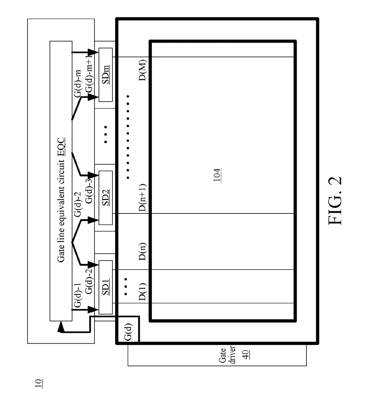
However, the gate signal may be attenuated during transmission, resulting in that the gate signal has different transmitting delay times in different positions on the gate line.
As a result, it is not easy for the source output signal to cooperate with the gate signal for output, leading to operational errors of the display device.

Method used


Image

  • Source driver, display device, delay method of source output signal, and drive method of display device
  • Source driver, display device, delay method of source output signal, and drive method of display device
  • Source driver, display device, delay method of source output signal, and drive method of display device

Examples


Embodiment Construction

[0019]The spirit of the disclosure is clearly described below with reference to the accompanying drawings and detailed statement; any person of ordinary skill in the art can make changes and modifications according to the technology taught by the disclosure after understanding embodiments of the disclosure, which do not depart from the spirit and scope of the disclosure.

[0020]The terms “first”, “second”, . . . and the like used herein neither particularly refer to an order or a sequence nor are used to limit the present invention, which are merely intended to distinguish elements or operations described with the same technical terms.

[0021]The expression “electrical coupling” used herein may refer to that two or more elements make physical or electrical contact with each other directly or indirectly, and the expression “electrical coupling” may also refer to that two or more elements inter-operate or interact.

[0022]The expressions “comprise”, “include”, “have” and the like used herei...


PUM


Abstract

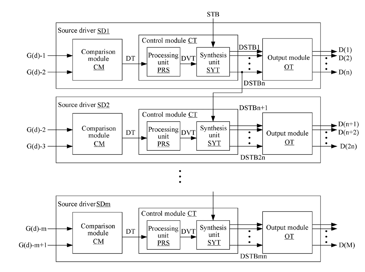
A drive method for a source signal including: acquiring a transmitting delay time of a gate signal; generating a plurality of delayed trigger signal according to the transmitting delay time of the gate signal, and sequentially outputting a plurality of delayed source signal to a plurality of pixel circuit according to the delayed trigger signal.

Description

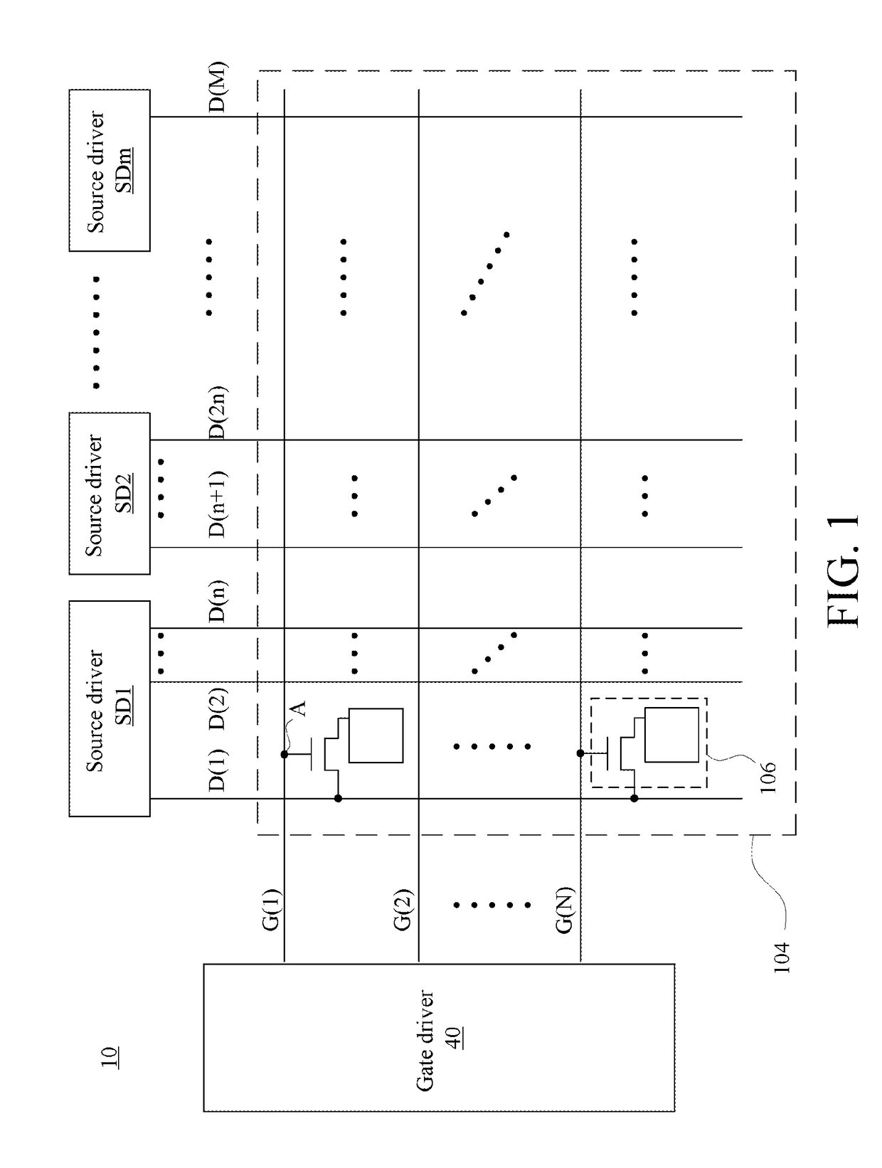
BACKGROUND[0001]Technical Field[0002]The present application relates to an electronic device and method, and more particularly to a source driver, a display device, a delay method of a source output signal and a drive method of a display device.[0003]Related Art[0004]With development of science and technology, display devices have been widely used in people's life.[0005]A typical display device may include a gate driver and a source driver. The gate driver is used for providing a gate signal to an active region, to turn on a pixel circuit of the active region. The source driver is used for providing a source output signal to the turnned pixel circuit in the active region, to display the pixel circuit in the active region corresponding to the voltage of the source output signal.[0006]However, the gate signal may be attenuated during transmission, resulting in that the gate signal has different transmitting delay times in different positions on the gate line. As a result, it is not ea...

Claims


Application Information

Patent Timeline
Patent Type & Authority Applications(United States)
IPC IPC(8): G09G3/20
CPCG09G2320/04G09G3/2092G09G3/20G09G2310/0275G09G2320/0223
Inventor HUNG, CHIH-HAOWANG, HUNG-CHIYANG, CHIH-HSIANG
Owner AU OPTRONICS CORP
Learn More