
Control system for chemical heat accumulator

a control system and heat accumulator technology, applied in the direction of heat storage plants, stationary conduit assemblies, lighting and heating apparatus, etc., can solve the problems of heat release and heat accumulation according to the temperature, and achieve the effect of effective heat accumulation

Inactive Publication Date: 2017-08-24
TOYOTA JIDOSHA KK
View PDF6 Cites 0 Cited by
  • Summary
  • Abstract
  • Description
  • Claims
  • Application Information

AI Technical Summary

Benefits of technology

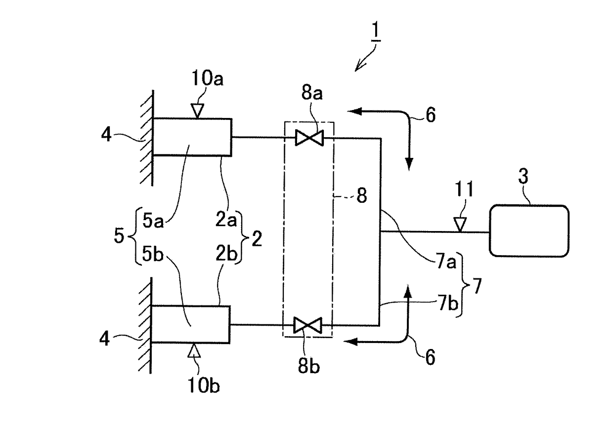
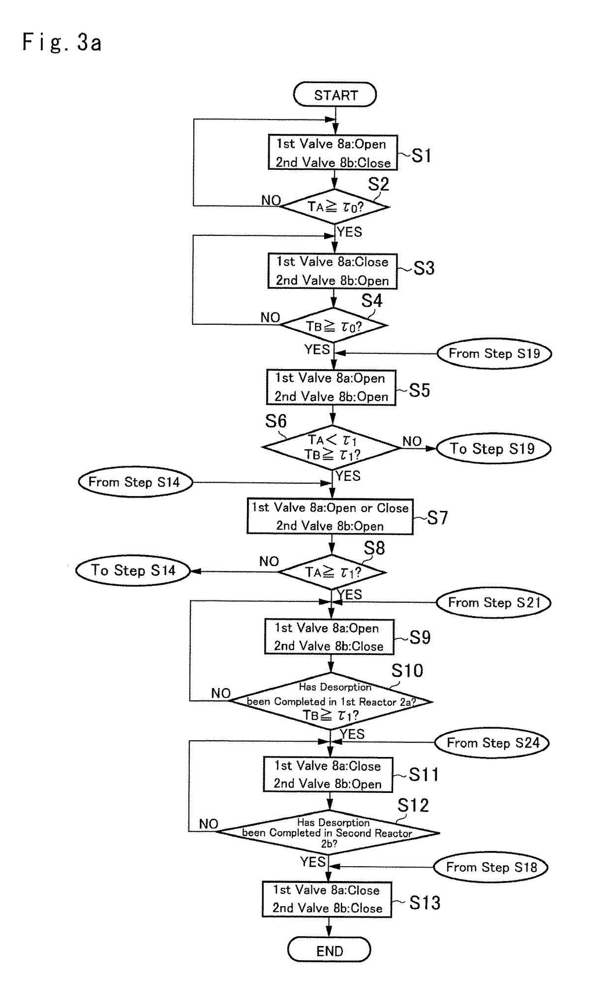
The present invention is about a control system for a chemical heat accumulator that releases heat through an exothermic reaction between a reaction material and a reaction medium, and accumulates heat through desorption of the reaction medium from the reaction material. The control system includes multiple reactors, a reservoir that stores the reaction medium, and a valve mechanism that can communicate each reactor separately with the reservoir. By controlling the valve mechanism, the system can prioritize the heat release or accumulation in certain reactors, based on their location and timing. This results in more efficient heat handling and reduced impact of other reactions. The overall arrangement of the system is simplified, and the size is made smaller. The control system has a non-limiting embodiment that enables more flexible prioritization of heat release or accumulation in different reactors.

Problems solved by technology

However, even when the temperature conditions for heating and accumulating heat are same or close, the degree of priority of heat release and heat accumulation of the reactor provided at each location is different, and moreover, if the degree of priority of the heat release and heat accumulation of the reactor and the temperature conditions do not match, the reaction medium is stored in a reactor having a low degree of priority rather than being stored in a reactor having a high degree of priority for heat release and heat accumulation, or the reaction medium is desorbed from the reactor having a low degree of priority, thereby leading to a possibility of the heat release and heat accumulation according to the degree of priority not being carried out.

Method used


Image

  • Control system for chemical heat accumulator
  • Control system for chemical heat accumulator
  • Control system for chemical heat accumulator

Examples


Embodiment Construction

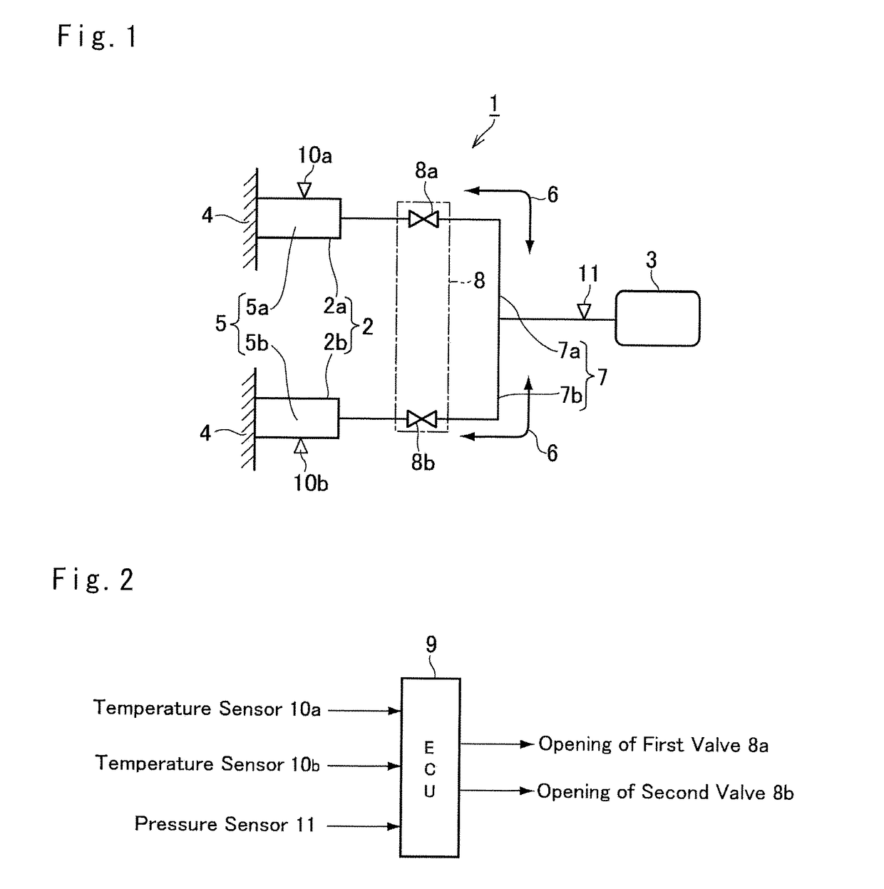
[0035]An embodiment of a chemical heat accumulator according to the present application is shown schematically in FIG. 1. The chemical heat accumulator 1 shown here has a plurality of reactors 2 and an adsorber 3 used in common with the reactors 2. Two reactors 2a and 2b are shown in FIG. 1. The reactors 2a and 2b are fitted to a heating portion 4 to exchange heat with the heating portion 4.

[0036]The reactors 2a and 2b contain reaction materials (also referred to as the “heat storage materials”) 5a and 5b to carry out an exothermic reaction and an endothermic reaction reversibly. The exothermic reaction occurs by chemically combining the reaction materials 5a and 5b with a reaction medium 6, and the endothermic reaction occurs by the reaction medium 6 being separated (desorbed) from the reaction materials 5a and 5b. The reaction materials 5a and 5b to carry out such chemical reactions may be substances such as Mg, CaO, and FeCl2 used in the conventional chemical heat accumulator, an...


PUM


Abstract

There is provided a control system of a chemical heat accumulator which enables to facilitate small-sizing of the chemical heat accumulator by carrying out heat release and heat accumulation according to a degree of priority by appropriately selecting a location of carrying out the heat release and heat accumulation on priority basis. A chemical heat accumulator includes a valve mechanism which makes a plurality of reactors communicate separately with a reservoir, and cuts off the plurality of reactors from the reservoir. When both reactors are in a state in which an exothermic reaction between a reaction material and a reaction medium is possible, or in a state in which an endothermic reaction in which the reaction medium is desorbed is possible, a controller which controls an opening of a valve mechanism controls the opening of the valve mechanism such that a flow rate of the reaction medium circulated between the first reactor and the reservoir for which a degree of priority of heat release or heat accumulation is high becomes higher than a flow rate of the reaction medium circulated between the second reactor and the reservoir for which the degree of priority of heat release or heat accumulation is low.

Description

CROSS REFERENCE TO RELATED APPLICATIONS[0001]The present application claims the benefit of Japanese Patent Application No. 2016-029155 filed on Feb. 18, 2016 with the Japanese Patent Office, the disclosures of which are incorporated herein by reference in its entirety.BACKGROUND[0002]Field of the Disclosure[0003]Embodiments of the present invention relate to a control system for a chemical heat accumulator that releases and accumulates heat utilizing a reversible chemical reaction between a reaction material and a reaction medium.[0004]Discussion of the Related Art[0005]Systems of this type have been described in Japanese Patent Application Laid-open Publication No. 2014-227861. In the system described in Japanese Patent Application Laid-open Publication No. 2014-227861, a first reactor containing a first reaction material is fitted to an object to be heated, and by supplying a first reaction medium from a first reservoir to the first reactor, heat is generated by a reaction between...

Claims


Application Information

Patent Timeline
Patent Type & Authority Applications(United States)
IPC IPC(8): F28D20/00F28D1/02
CPCF28D1/0226F28D20/003F28F27/00Y02E60/14
Inventor AMANO, TAKASHIAIKAWA, HIDEFUMIHASEGAWA, YOSHIOKASHIWAKURA, JUMPEI
Owner TOYOTA JIDOSHA KK
Learn More