Camera module
- Summary
- Abstract
- Description
- Claims
- Application Information
AI Technical Summary
Benefits of technology
Problems solved by technology
Method used
Image

Examples
embodiment 1
[0040]Hereinafter, an embodiment of the invention will be described on the basis of FIG. 1 to FIG. 4.
(Overview of Camera Module)
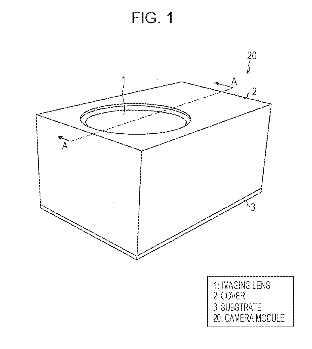
[0041]FIG. 1 is a perspective view illustrating a schematic configuration of a camera module 20.
[0042]As illustrated in the figure, the camera module 20 is provided with imaging lenses 1, a cover 2 that accommodates, in the inside thereof, a lens driving device (not illustrated) which is arranged outside the imaging lenses 1 for driving the imaging lenses 1 in an optical axis direction, and a substrate 3 on which an image sensor (not illustrated), the lens driving device (not illustrated), and the cover 2 are mounted. Note that, in the description below, a side of the imaging lenses 1 (object side) is referred to as an upper side and a side of the substrate 3 is referred to as a lower side, for convenience.
(Lens Driving Device)
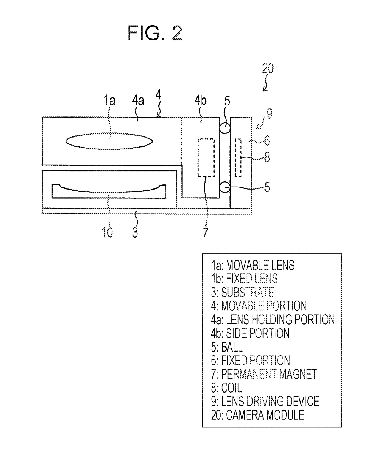
[0043]FIG. 2 is a schematic side view for explaining a lens driving device 9 of the camera module 20. Note that, since FIG. 2 is the...
embodiment 2
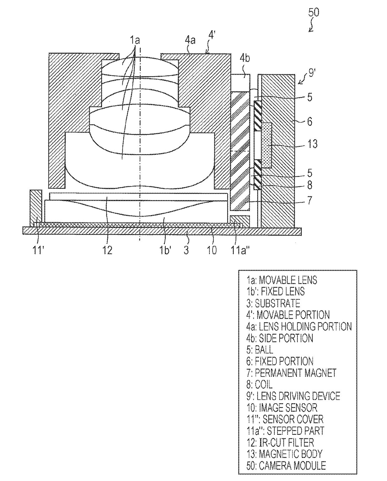
[0067]Next, Embodiment 2 of the invention will be described on the basis of FIG. 5 and FIG. 6. The present embodiment is different from Embodiment 1 described above in that a part of a flange part of a fixed lens 1b′ is subjected to D-cut and the part subjected to D-cut is arranged on a side closer to a driving portion (the permanent magnet 7 and the coil 8) of a lens driving device 9′. With such a configuration, it is possible to reduce a distance between the center of an optical axis and the driving portion (the permanent magnet 7 and the coil 8) of the lens driving device 9′. Other configurations are the same as those described in Embodiment 1. For convenience of description, members having the same functions as those of the members illustrated in the figures of Embodiment 1 above are denoted by the same reference signs, and description thereof will be omitted.
[0068]FIG. 5 is a sectional view illustrating a schematic configuration of a camera module 30, and FIG. 6 is a plan view ...
embodiment 3
[0075]Next, Embodiment 3 of the invention will be described on the basis of FIG. 7. The present embodiment is different from Embodiments 1 and 2 described above in that a spring is used as a guide, by which the movable lens 1a is movable in an optical axis direction, instead of using the balls and the V-grooves. Other configurations are the same as those described in Embodiments 1 and 2. For convenience of description, members having the same functions as those of the members illustrated in the figures of Embodiments 1 and 2 above are denoted by the same reference signs, and description thereof will be omitted.
[0076]FIG. 7 is a sectional view illustrating a schematic configuration of a camera module 40.
[0077]As illustrated in the figure, in the camera module 40, one ends of a pair of plate springs 14a and 14b are arranged on upper and lower surfaces of a side portion 4e of a movable portion 4″, and the other ends of the plate springs 14a and 14b are connected to the fixed portion 6 ...
PUM
 Abstract
Description
Claims
Application Information
 - R&D
- Intellectual Property
- Life Sciences
- Materials
- Tech Scout
- Unparalleled Data Quality
- Higher Quality Content
- 60% Fewer Hallucinations
Browse by: Latest US Patents, China's latest patents, Technical Efficacy Thesaurus, Application Domain, Technology Topic, Popular Technical Reports.
© 2025 PatSnap. All rights reserved.Legal|Privacy policy|Modern Slavery Act Transparency Statement|Sitemap|About US| Contact US: help@patsnap.com