
Woodworking Spindle, Moulding Machine with such a Spindle, and Method Using such a Spindle

a technology of spindle and spindle shaft, which is applied in the field of woodworking spindle, can solve the problems of rotary bearings which support the spindle shaft in the spindle housing being partially subjected to great forces, and affecting the operation of the machin

Active Publication Date: 2017-08-10
MICHAEL WEINIG AG
View PDF8 Cites 3 Cited by
  • Summary
  • Abstract
  • Description
  • Claims
  • Application Information

AI Technical Summary

Benefits of technology

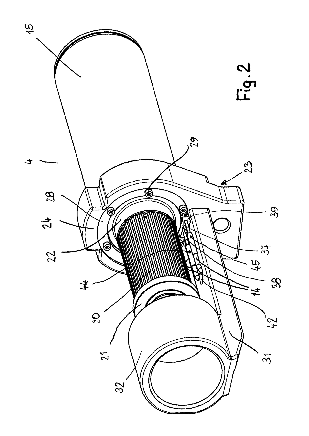
The spindle in this invention has a temperature sensor to monitor the temperature of its bearings. This helps to determine if the bearings are reaching a critical point during operation. By monitoring the temperature, the user is alerted in advance that the spindle may need further use. The data collected by the temperature sensor is stored and can be easily retrieved by a smart device. This improves the reliability of the spindle and its performance.

Problems solved by technology

During woodworking, the rotary bearings which support the spindle shaft in the spindle housing are partially subjected to great forces.
This can lead to the rotary bearings becoming damaged.
When a damaged rotary bearing is not recognized, this leads to failure of the corresponding spindle which requires extended periods of downtime of the machine as well as high repair costs.
Due to a damaged rotary bearing, surrounding parts within the machine are possibly also impaired, possibly even damaged.

Method used


Image

  • Woodworking Spindle, Moulding Machine with such a Spindle, and Method Using such a Spindle
  • Woodworking Spindle, Moulding Machine with such a Spindle, and Method Using such a Spindle
  • Woodworking Spindle, Moulding Machine with such a Spindle, and Method Using such a Spindle

Examples


Embodiment Construction

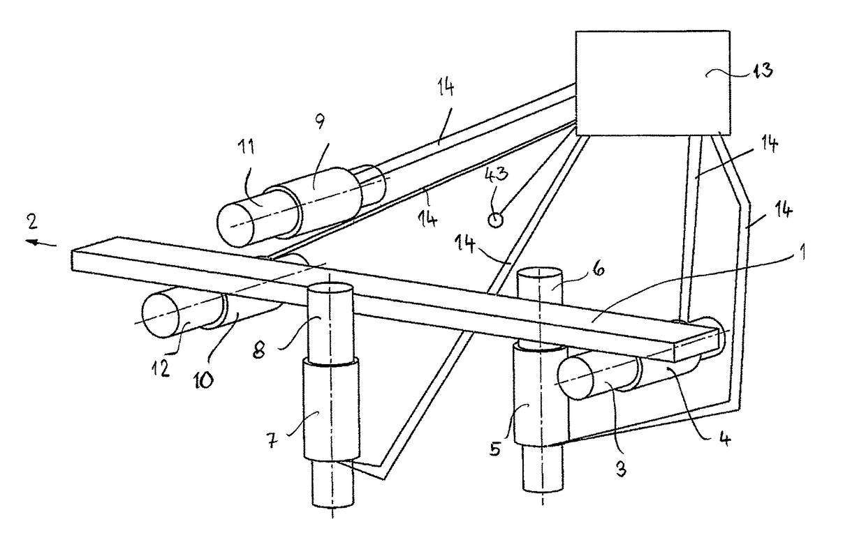
[0034]FIG. 1 shows in schematic illustration a moulding machine with which workpieces 1 of wood, plastic material and the like, that are rectangular in cross section, can be machined on all four sides in a continuous process. FIG. 1 shows only the spindles and the tools, seated thereon and schematically indicated, with which the workpiece machining is carried out. The transport elements, supports for the workpieces, and the like are not shown for clarity. The workpieces 1 are transported in transport direction of arrow 2 through the moulding machine. First, the bottom side of the workpieces 1 is machined by a tool 3 which is seated on a horizontal spindle 4. With the tool 3, the workpiece 1 is planed straight, for example. In transport direction (arrow 2) downstream of the lower horizontal spindle 4, a vertical right spindle 5 is provided that carries a tool 6 with which the right longitudinal side of the workpiece 1 in the transport direction (arrow 2) is machined as the workpiece ...


PUM

PropertyMeasurementUnit
temperatureaaaaaaaaaa
inner temperatureaaaaaaaaaa
forcesaaaaaaaaaa

Abstract

A woodworking spindle has a spindle shaft disposed in a spindle housing. One or more rotary bearings support the spindle shaft in the spindle housing. One or more temperature sensors are provided that detect the temperature of the one or more rotary bearings. An evaluation unit is provided and temperature signals generated by the temperature sensors are supplied to the evaluation unit that generates output signals based on evaluation of the temperature signals generated by the temperature sensors. In a method for monitoring the temperature of rotary bearings of a spindle of a woodworking machine, the temperature of the rotary bearings is permanently detected and rotary bearing temperature signals are generated. The rotary bearing temperature signals are sent to an evaluation unit and compared with a first temperature limit value. A first output signal is generated when the temperature signals reach a first temperature limit value.

Description

BACKGROUND OF THE INVENTION[0001]The invention concerns a woodworking spindle comprising a spindle housing in which a spindle shaft is supported by at least one rotary bearing; a moulding machine comprising spindles for machining elongate workpieces of wood, plastic material and the like in a continuous process in which the workpieces are machined at the longitudinal sides; as well as a method for monitoring the temperature of at least one rotary bearing of the spindle of a woodworking machine.[0002]In woodworking machines, in particular moulding machines, spindles are employed with which tools required for machining are rotatably driven. The spindles have a spindle shaft which is rotatably supported in a spindle housing. During woodworking, the rotary bearings which support the spindle shaft in the spindle housing are partially subjected to great forces. This can lead to the rotary bearings becoming damaged. When a damaged rotary bearing is not recognized, this leads to failure of ...

Claims


Application Information

Patent Timeline
Patent Type & Authority Applications(United States)
IPC IPC(8): G01M13/04F16C41/00B27C1/08
CPCG01M13/04B27C1/08F16C2322/39F16C2233/00F16C41/00B23Q17/00B27C9/04B27C5/10B27G21/00B23Q1/70B23Q17/0985
Inventor DAWIDZIAK, ALBRECHTKLEIN, HUBERT
Owner MICHAEL WEINIG AG
Learn More