
System for switching between a single node pcie mode and a multi-node pcie mode

a pcie mode and multi-node technology, applied in the field of transmission architectures, can solve the problem of not being able to enable multiple endpoints to access a single endpoint simultaneously

Active Publication Date: 2017-07-27
QUANTA COMPUTER INC
View PDF13 Cites 54 Cited by
  • Summary
  • Abstract
  • Description
  • Claims
  • Application Information

AI Technical Summary

Benefits of technology

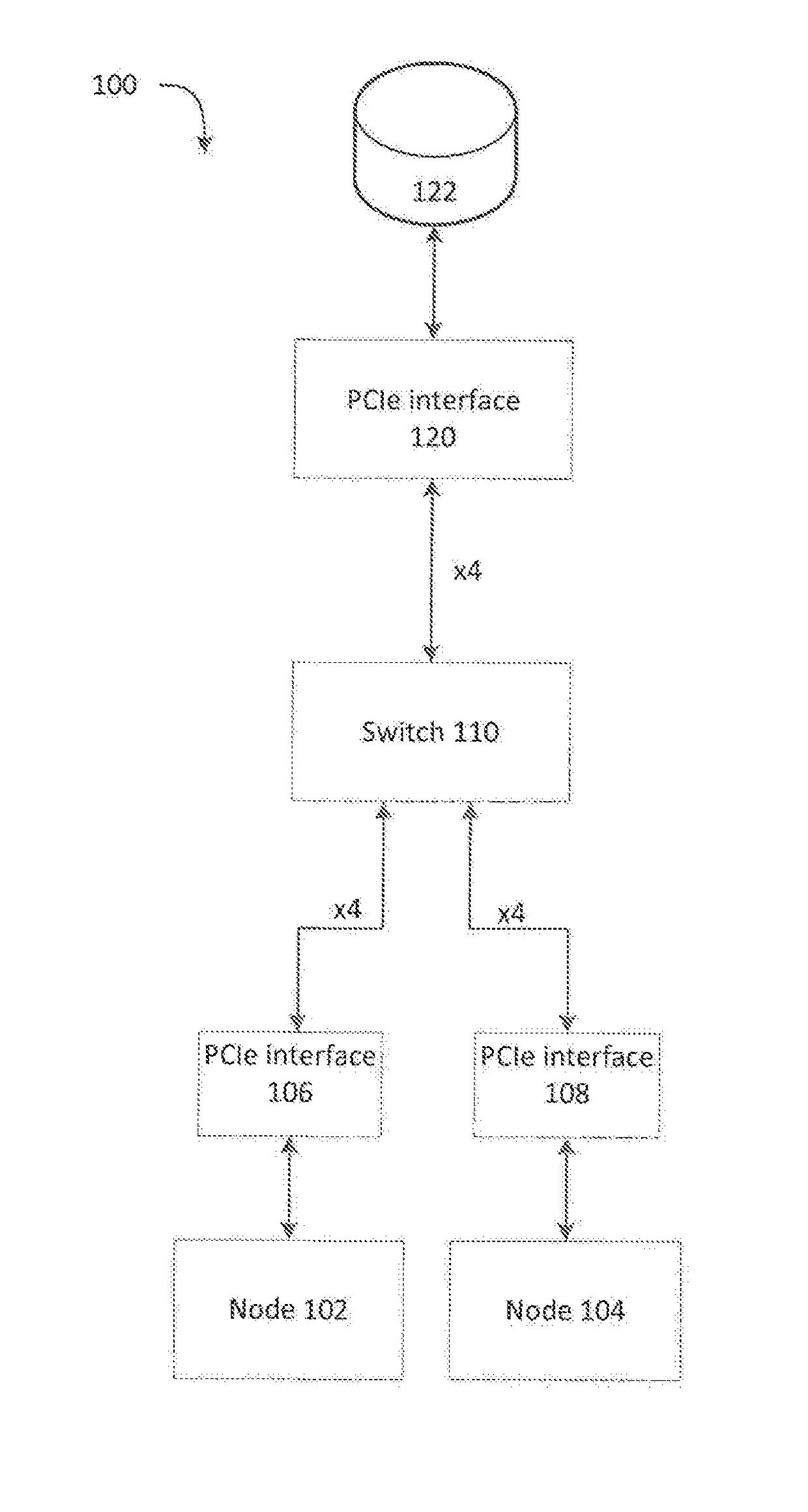
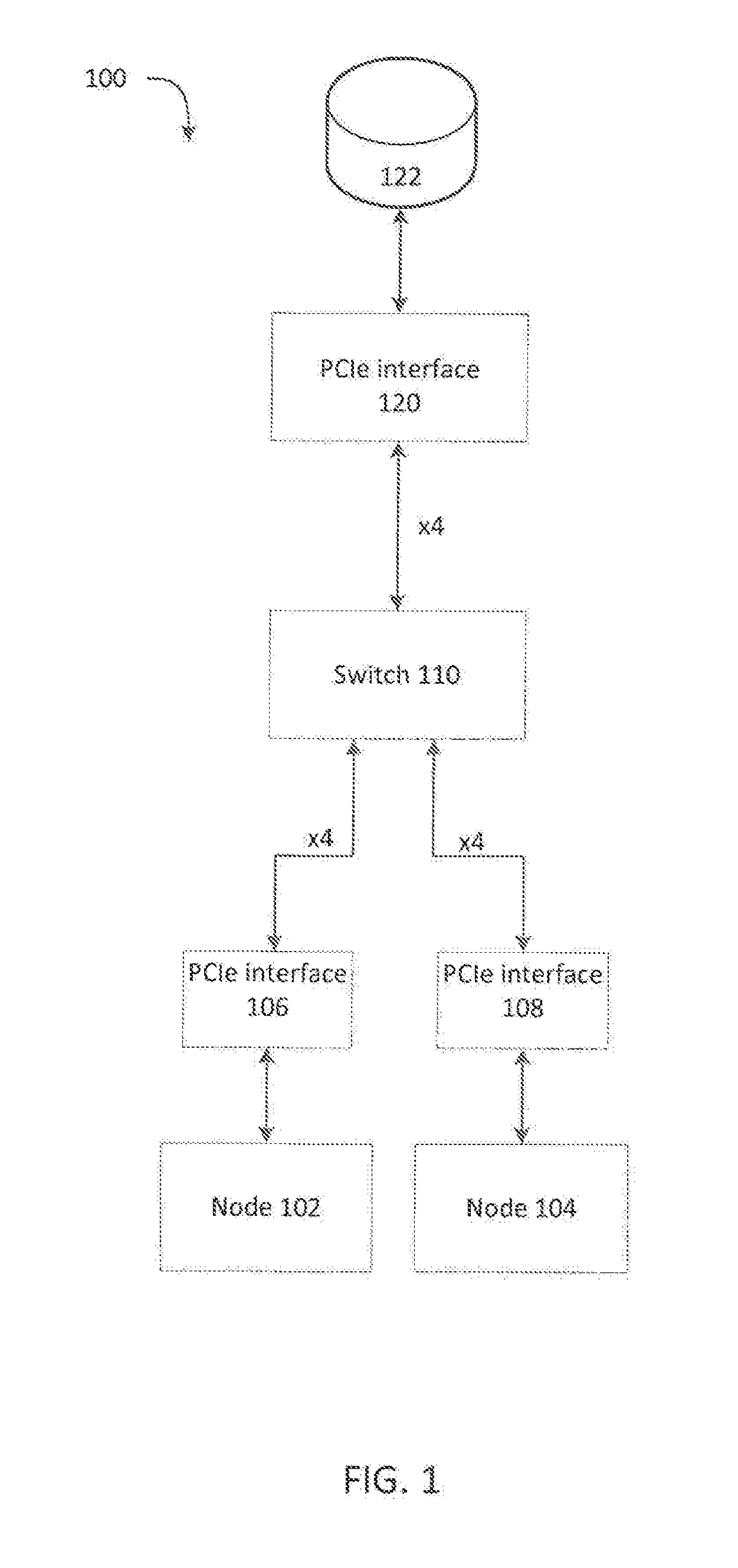
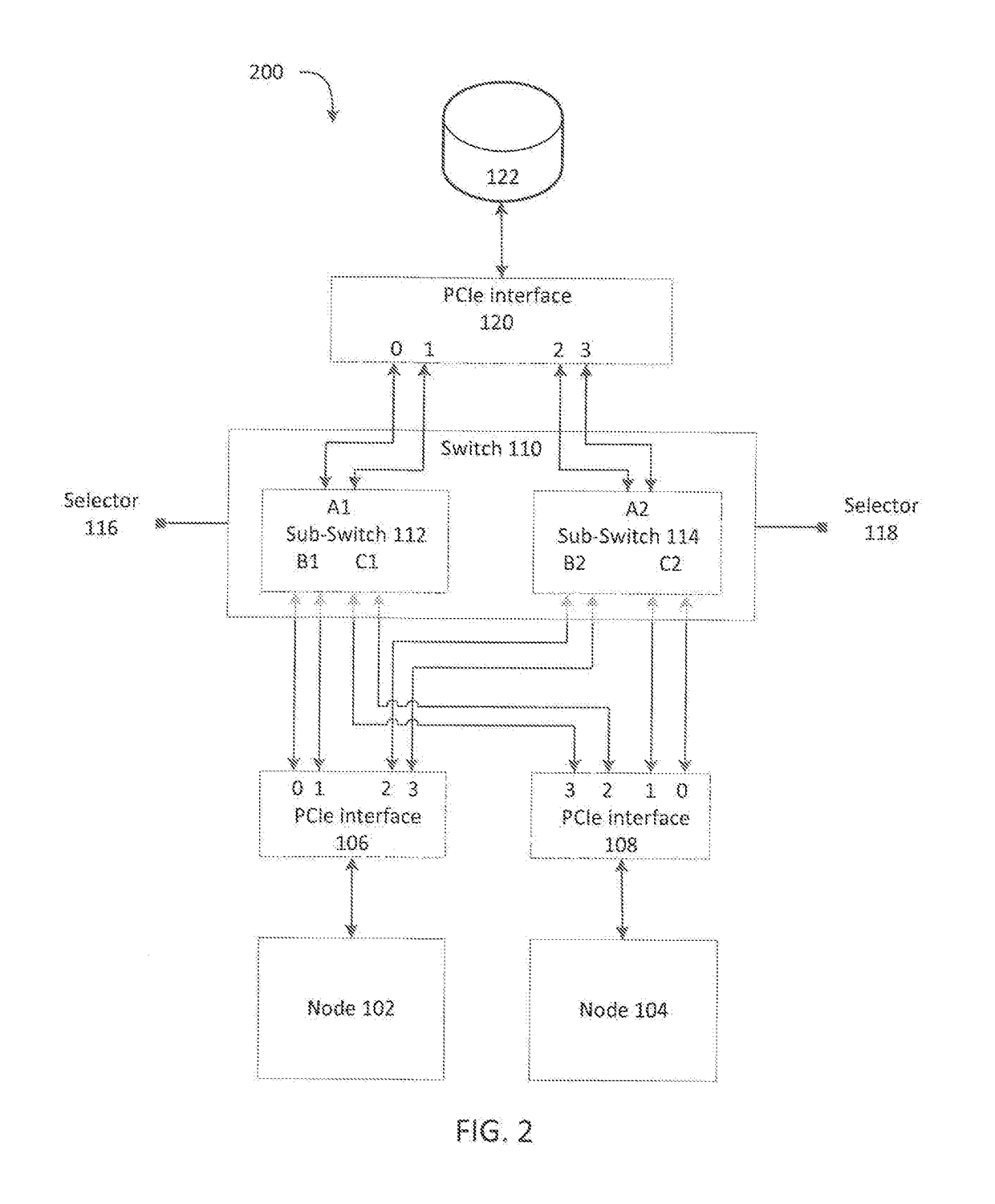
The patent describes a system, method, and computer-readable medium for switching between a single node PCIe transmission mode and a multi-node PCIe transmission mode. The system includes a switch module that can selectively couple lanes of different devices to enable the desired transmission mode. The switch module can route the enabled lanes in a specific order, and the number of enabled lanes can be equal to or different from the number of available lanes. The system can be used in a computer system with PCIe interfaces and NVMe SSDs. The technical effect of this patent is to provide a flexible and efficient way to switch between different PCIe transmission modes.

Problems solved by technology

While PCIe switches can enable multiple endpoints access to a single endpoint, there is currently no way to enable multiple endpoints access to a single endpoint simultaneously.

Method used


Image

  • System for switching between a single node pcie mode and a multi-node pcie mode
  • System for switching between a single node pcie mode and a multi-node pcie mode
  • System for switching between a single node pcie mode and a multi-node pcie mode

Examples


Embodiment Construction

[0022]Additional features and advantages of the disclosure will be set forth in the description which follows, and in part will be obvious from the description, or can be learned by practice of the herein disclosed principles. The features and advantages of the disclosure can be realized and obtained by means of the instruments and combinations particularly pointed out in the appended claims. These and other features of the disclosure will become more fully apparent from the following description and appended claims, or can be learned by the practice of the principles set forth herein.

[0023]Several definitions that apply throughout this disclosure will now be presented. The term “coupled” is defined as connected, whether directly or indirectly through intervening components, and is not necessarily limited to physical connections. The term “comprising” means “including, but not necessarily limited to”; it specifically indicates open-ended inclusion or membership in a so-described com...


PUM


Abstract

A system for switching between a high performance mode and dual path mode is disclosed. The system includes a first device, a second device, a third device, and a switch configured to receive control signals, and in response causing the switch to selectively couple one or more first lanes of the first device or one or more second lanes of the second device to third lanes of the third device to yield enabled lanes. The system also include a number of the enabled lanes is less than or equal to a number of the third lanes, and the switch is configured to route the enabled lanes associated with the first device to a first portion of the third lanes in an increasing order and to route the enabled lanes associated with the second device to a second portion of the third lanes in a decreasing order.

Description

FIELD OF THE INVENTION[0001]The subject matter herein generally relates to transmission architectures for communicating through peripheral component interconnect express buses to non-volatile memory express solid-state drives. More specifically, the subject matter relates to hardware architecture configured to enable switching between a single node transmission mode and a multi-node transmission mode.BACKGROUND[0002]Peripheral Component Interconnect Express (PCIe) is a high-speed serial computer expansion bus standard. PCIe improves on older bus standards by including a higher maximum system bus throughput, lower input / output pin counter, a smaller physical footprint, and better performance scaling for bus devices. One of the key differences between PCIe and the older bus standards is PCIe is based on point-to-point topology (i.e., opposed to a shared parallel bus architecture). Each PCIe bus can include a number of different lanes (e.g., x1, x2, x4, x8, x16, x32). A lane is compose...

Claims


Application Information

Patent Timeline
Patent Type & Authority Applications(United States)
IPC IPC(8): G06F13/40G06F13/28G06F12/02G06F13/42
CPCG06F13/4022G06F13/4282G06F2212/7208G06F12/0246G06F13/287G06F13/1668G06F13/42
Inventor CHU, WEI-YICHENG, CHIA-FENGCHANG, KAICHEN, CHIH-YU
Owner QUANTA COMPUTER INC
Learn More