This helps you quickly interpret patents by identifying the three key elements:
Problems solved by technology
Method used
Benefits of technology
The present patent describes a pouch with a specific design that allows for the separation of liquids and solid elements. The pouch has a space between the bonding points along its transverse axis, which prevents liquids from being trapped and allows for the passage of solid elements. This design also allows for easy separation of liquids with different densities, by tilting the pouch and creating a gravity separation effect. The technical effect of this patent is to provide a more hygienic and efficient pouch for receiving liquid mixtures containing solid elements.
Problems solved by technology
Furthermore, since the valve has a plurality of overlapping pairs of sheets, if a small quantity of liquid penetrates between the outer pair of sheets and the pair of sheets nested within, the liquid will tend to remain trapped between these two pairs of sheets.
That configuration presents drawbacks.
Indeed, the small spacing between the bonding points tends to limit the passage of the liquid while it is being inserted into the pouch, which may impede proper use of the pouch.
Furthermore, when the liquid contains solid elements (solid elements in vomit, clots of blood in urine, etc.), the bonding points can impede or even prevent those solid elements from passing through.
Method used
Image
Click on the blue label to locate the original text in one second.
Reading with bidirectional positioning of images and text.
Examples
second embodiment
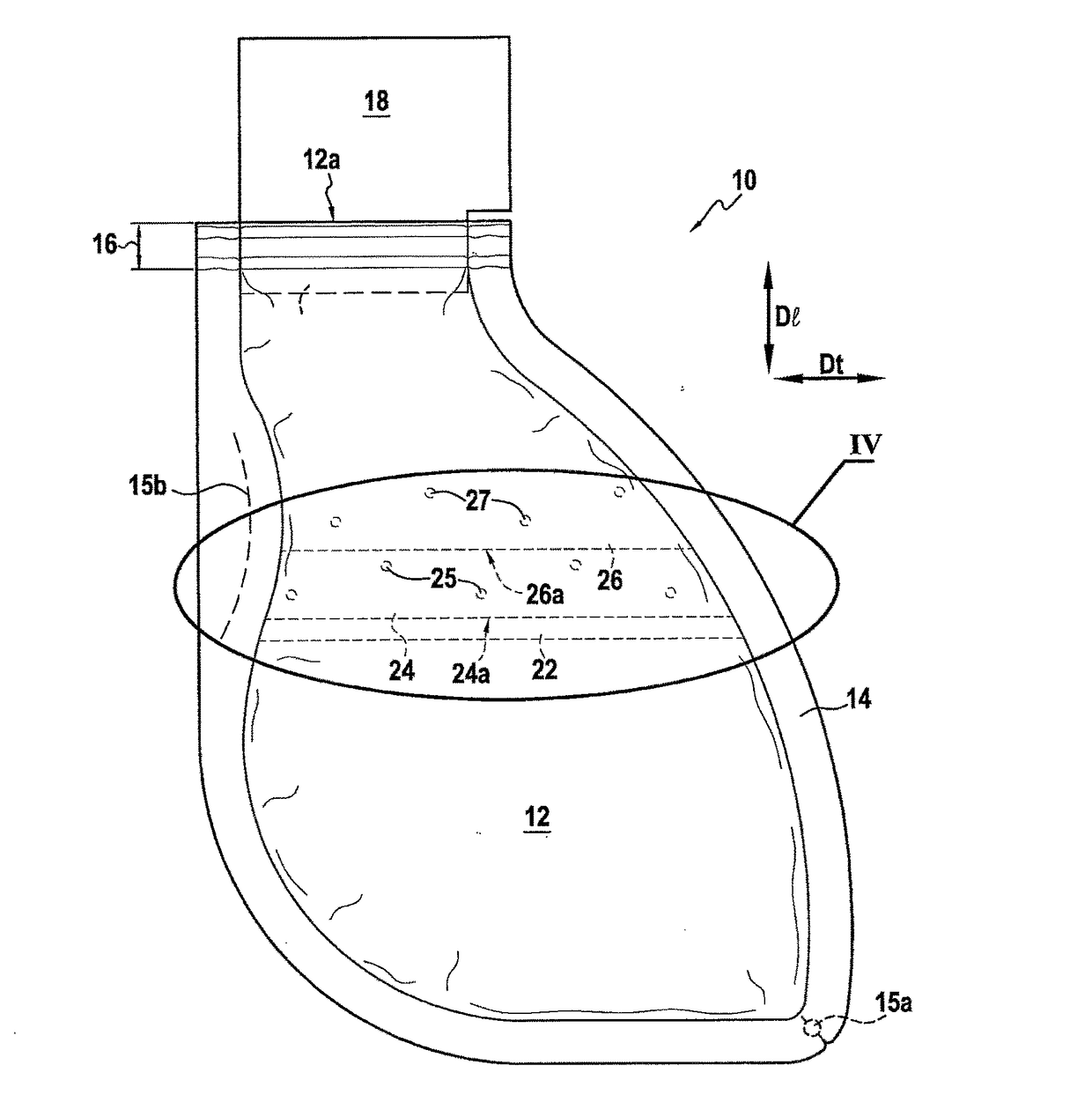
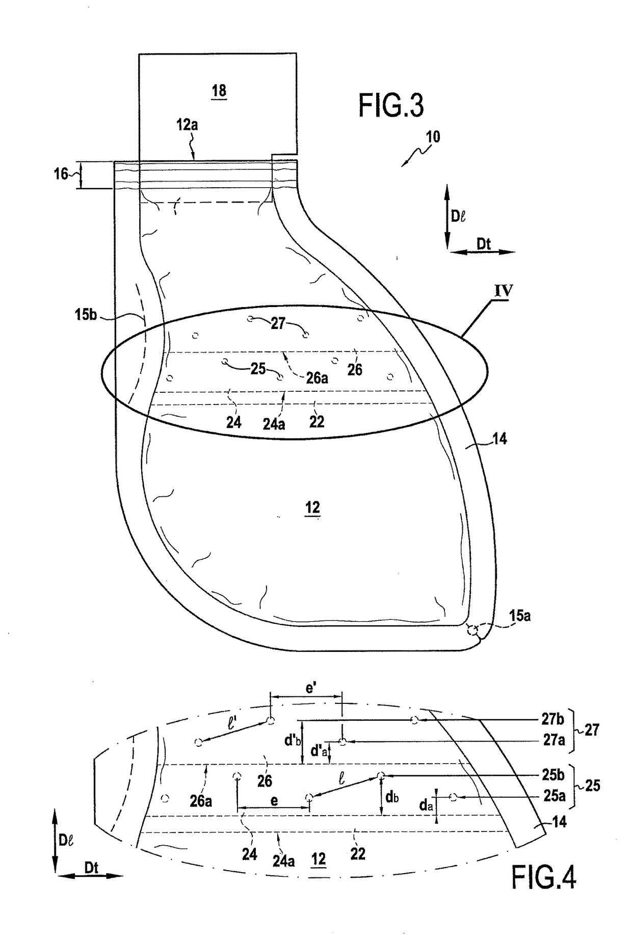
[0065]In a second embodiment, shown in FIG. 3, the valve also has a third pair of sheets 26 extending across the entire width of the pouch in the regions where they are to be found, and welded to the walls of the bag by the weld line 14. In particular, the proximal ends (closer to the opening 12a) of the sheets of the pair of sheets 26 are secured to a wall of the bag in the vicinity of the opening 12a by the weld line 14.
[0066]The third pair of sheets 26 extends inside the pair of sheets 24, the sheets of the third pair of sheets 26 being shorter than the sheets of the pair of sheets 24. The sheets of the first and second pairs of sheets 22 and 24 are locally bonded together by the primary bonding points 25, as described above.
[0067]The first, second, and third pairs of sheets 22, 24, and 26 are locally bonded together at a plurality of secondary bonding points 27 in the vicinity of the distal end 26a of the pair of sheets 26.
[0068]The sheets of the third pair of sheets 26 may be m...
third embodiment
[0088]In a third embodiment, shown in FIG. 5, the bonding points 25 and 27 are arranged in such a manner that the spacing between two successive neighboring primary bonding points 25 increases in a given direction along the transverse axis Dt starting from the edge d′ of the bag 12 formed by the weld line 14 in the proximity of the line of weakness 15b and going to the other edge of the bag 12 formed by the weld line 14, and the spacing between two successive neighboring secondary bonding points 27 increases in the same direction along the transverse axis Dt.
[0089]More precisely, and as shown in FIG. 5, the successive spacings e1, e2, e3, . . . between successive neighboring primary bonding points 25 are such that:
e1≦e2≦e3≦ . . .
[0090]Likewise, the successive spacings e′1, e′2, e′3, . . . between successive neighboring secondary bonding points 27 are such that:
e′1≦e′2≦e′3≦ . . .
[0091]With this configuration, when the pouch 10 is tilted towards the horizontal (i.e. such that the tran...
PUM
Property
Measurement
Unit
Flexibility
aaaaa
aaaaa
Distance
aaaaa
aaaaa
Abstract
A pouch (10) comprises a flexible bag (12) having an opening (12a) at one end, and a safety valve arranged inside the bag (12) to substantially prevent the content of the bag (12) leaving through the opening (12a). The valve comprises a first pair of sheets (22) and a second pair of sheets (24) that are bonded together locally at a plurality of spaced-apart primary bonding points (25), and a third pair of sheets (26), the first, second, and third pairs of sheets (22, 24, and 26) being bonded together locally at a plurality of spaced-apart secondary bonding points (27). The distance between the primary bonding points (25) and the distal end of the sheets of the second pair of sheets (24) varies along a transverse axis (Dt) of the bag (12).
Description
BACKGROUND OF THE INVENTION[0001]The present invention relates to a pouch comprising a flexible bag having an opening at one end, and a safety valve arranged inside the bag to substantially prevent the content of the bag from leaving through the opening.[0002]Pouches of this type are known, e.g. from European patents Nos. 0 748 620 or 0 847 742. They are used to receive substances generally in liquid form, in particular waste of human or animal origin such as urine or vomit.[0003]Such pouches are commonly made from thin sheets of plastics material (e.g. polyethylene) or of other flexible materials. They include a safety valve arranged inside the bag to substantially prevent the content of the bag leaving through the opening, e.g. when the pouch is accidentally turned upside-down.[0004]Such a valve comprises at least two nested pairs of sheets that are locally bonded together at a plurality of bonding points which are aligned parallel to and in the vicinity of one of the (rectilinear...
Claims
Application Information
Patent Timeline
Application Date:The date an application was filed.
Publication Date:The date a patent or application was officially published.
First Publication Date:The earliest publication date of a patent with the same application number.
Issue Date:Publication date of the patent grant document.
PCT Entry Date:The Entry date of PCT National Phase.
Estimated Expiry Date:The statutory expiry date of a patent right according to the Patent Law, and it is the longest term of protection that the patent right can achieve without the termination of the patent right due to other reasons(Term extension factor has been taken into account ).
Invalid Date:Actual expiry date is based on effective date or publication date of legal transaction data of invalid patent.