
Drag device for a dual-bearing reel

a dual-bearing, drag device technology, applied in the direction of reels, applications, fishing, etc., can solve the problems of increasing the force of the drag plate with respect to the drive gear, sound generated by interference, increasing the drag force, etc., to achieve the effect of reliably holding the sound generating member

Active Publication Date: 2017-07-20
SHIMANO INC
View PDF0 Cites 3 Cited by
  • Summary
  • Abstract
  • Description
  • Claims
  • Application Information

AI Technical Summary

Benefits of technology

The present invention relates to a drag device for a dual-bearing reel that is capable of reliably holding a sound generating member during a drag operation. This is achieved by a regulating portion of the housing member that regulates the movement of the head portion of the sound generating member in the circumferential direction, even when the gap between the drive gear and the drag plate is increased. The regulating portion has a pair of opposing surfaces or protrusions that face each other in the circumferential direction. This ensures that the drag device is able to hold the sound generating member in place during the drag operation and prevent it from falling out of the housing member. Overall, the present drag device provides a more robust and reliable solution for dragging the reel.

Problems solved by technology

In this state, when the head portion of the sound generating member interferes with the sound generating plate due to relative rotation between the drive gear and the drag plate, sound is generated by the interference.
In particular, as the drag plate approaches the drive gear, the pressing force of the drag plate with respect to the drive gear is increased, increasing the drag force.
In this state, if the head portion of the sound generating member interferes with the sound generating plate of the drag plate, the amount by which the shaft portion of the sound generating member protrudes from the housing member is increased, and there is a risk that the shaft portion of the sound generating member will fail out of the housing member.

Method used


Image

  • Drag device for a dual-bearing reel
  • Drag device for a dual-bearing reel
  • Drag device for a dual-bearing reel

Examples


Embodiment Construction

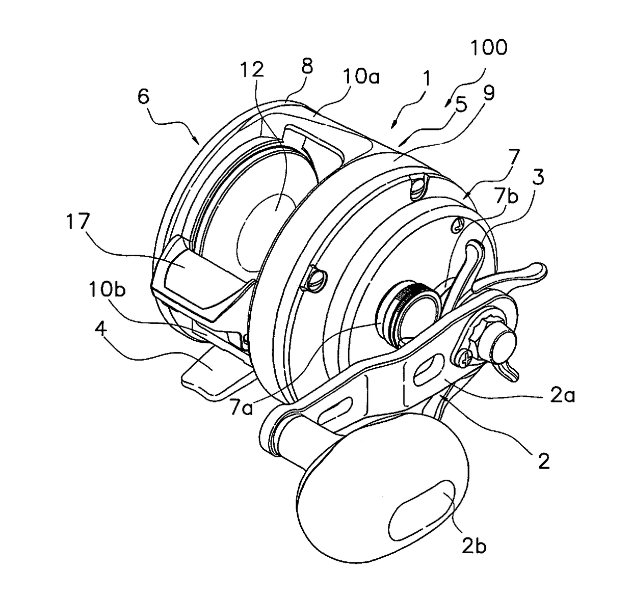
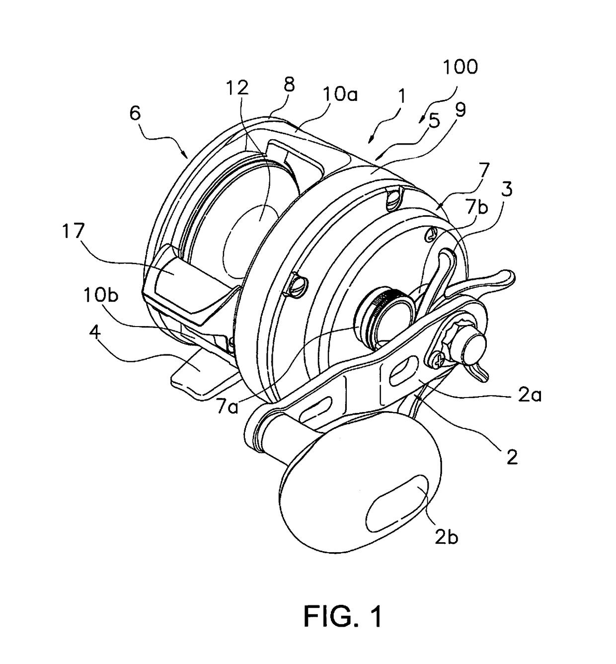
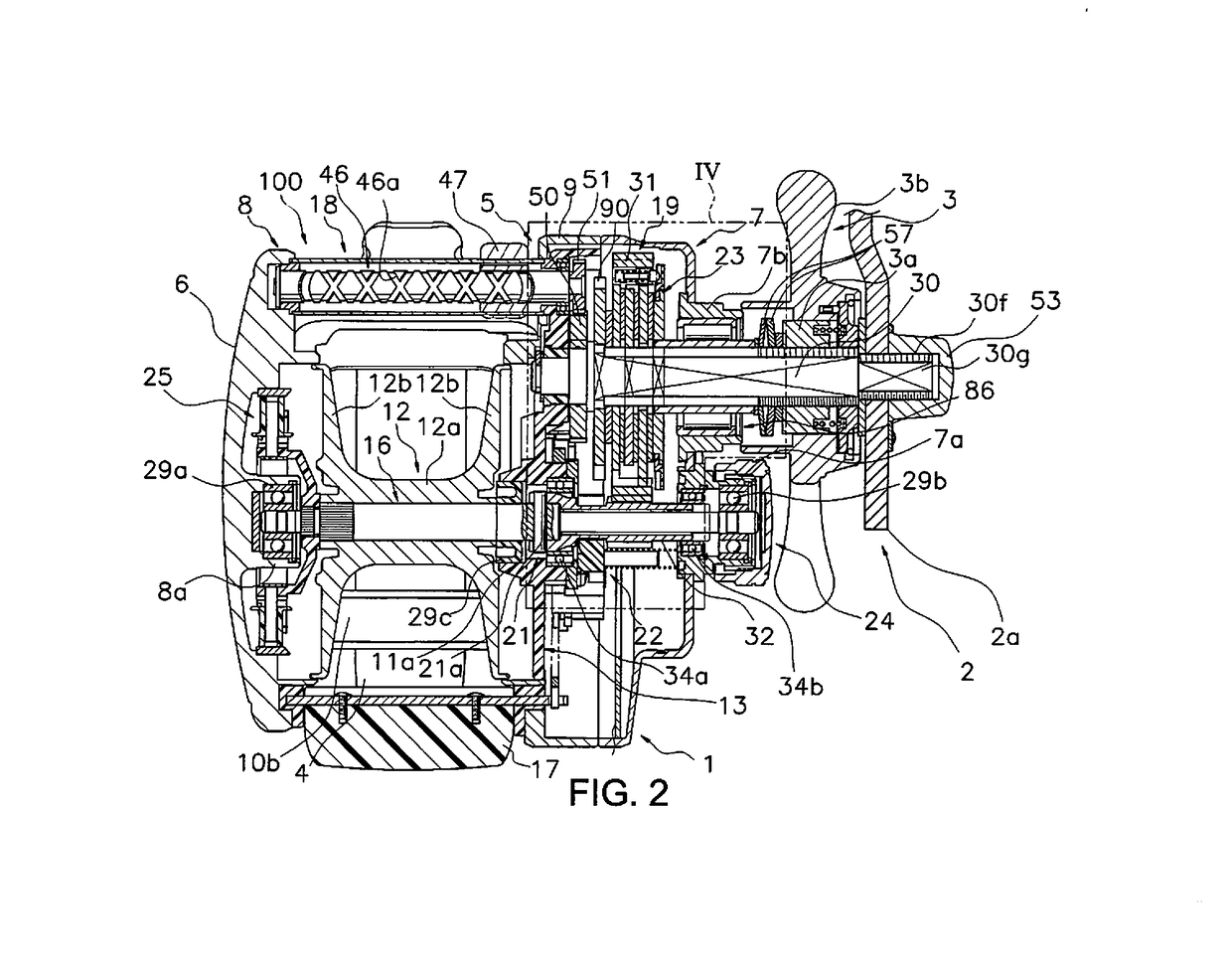
[0034]In FIG. 1 and FIG. 2, the dual bearing reel 100 that employs one embodiment of the present invention comprises a reel body 1, a handle 2 for rotating the spool disposed on the reel body 1 side, a spool 12, and a drag device 23.

Schematic Structure of the Dual-Bearing Reef

[0035]The reel body 1 comprises a frame 5, a first side cover 6 and a second side cover 7 that are mounted on both (opposite) sides of the frame 5, and a mechanism mounting plate 13. The frame 5 comprises a first side plate 8 and a second side plate 9 that are disposed so as to face each other with a prescribed gap therebetween, and an upper connecting portion 10a and a lower connecting portion 10b that couple the first side plate 8 and second side plate 9. A rod mounting leg portion 4 for mounting a fishing rod is integrally formed on the lower connecting portion 10b.

[0036]The first side cover 6 is substantially circular when seen from the axially outer side of the spool, and the second side cover is formed f...


PUM


Abstract

A drag device for a dual bearing reel includes a drag device, a sound generating member, and a housing member. The drag plate is integrally rotatable with the drive shaft, and is capable of being pressed by a drag adjustment member. The drag plate includes a sound generating plate opposed to the drive gear. The sound generating member includes a head portion configured to contact the sound generating plate, and a shaft portion connected to the head portion. The sound generating member is configured to generate a sound by interference between the sound generating plate and the head portion during relative rotation between the drive gear and the drag plate. The housing member is configured to be mounted to the drive gear and includes a holding portion to hold the shaft portion of the sound generating member, and a regulating portion configured to regulate movement of the head portion.

Description

CROSS-REFERENCE TO RELATED APPLICATIONS[0001]This application claims priority based on Japanese Patent Application No. 2016-009212, filed in the Japan Patent Office on Jan. 20, 2016, the contents of each of which are hereby incorporated herein by reference.BACKGROUND[0002]Field of the Invention[0003]The present invention relates to a drag device for a dual-bearing reel, and especially relates to a drag device for a dual bearing reel that regulates the relative rotation between a drive gear and a drive shaft[0004]Background Information[0005]Generally, a drag device is disposed on a drive shaft of a dual hearing reel to brake the rotation of the spool in the casting (line delivering) direction. The drag device adjusts the torque transmitted between the drive gear and the drive shaft to suppress the tensile force that is applied to the fishing line.[0006]The drag device comprises a drag adjustment member (star drag) and a drag plate that is integrally and rotatably mounted to the drive...

Claims


Application Information

Patent Timeline
IPC IPC(8): A01K89/033
CPCA01K89/05A01K89/051A01K89/056A01K89/053A01K89/033A01K89/01931A01K89/0192
Inventor TAKECHI, KUNIOIKUTA, TAKESHI
Owner SHIMANO INC
Learn More