
Blind rivet nut and fastening unit

a technology of rivet nut and bolt, which is applied in the direction of threaded fasteners, fastening means, dowels, etc., can solve the problems of no longer releasable parts, consequential damage, and transmission of torque for tightening bolts to the component to be fastened, so as to simplify the releasable fastening of components

Inactive Publication Date: 2005-05-17
GESIPA BLINDNIETTECHNIK GMBH
View PDF25 Cites 34 Cited by
  • Summary
  • Abstract
  • Description
  • Claims
  • Application Information

AI Technical Summary

Benefits of technology

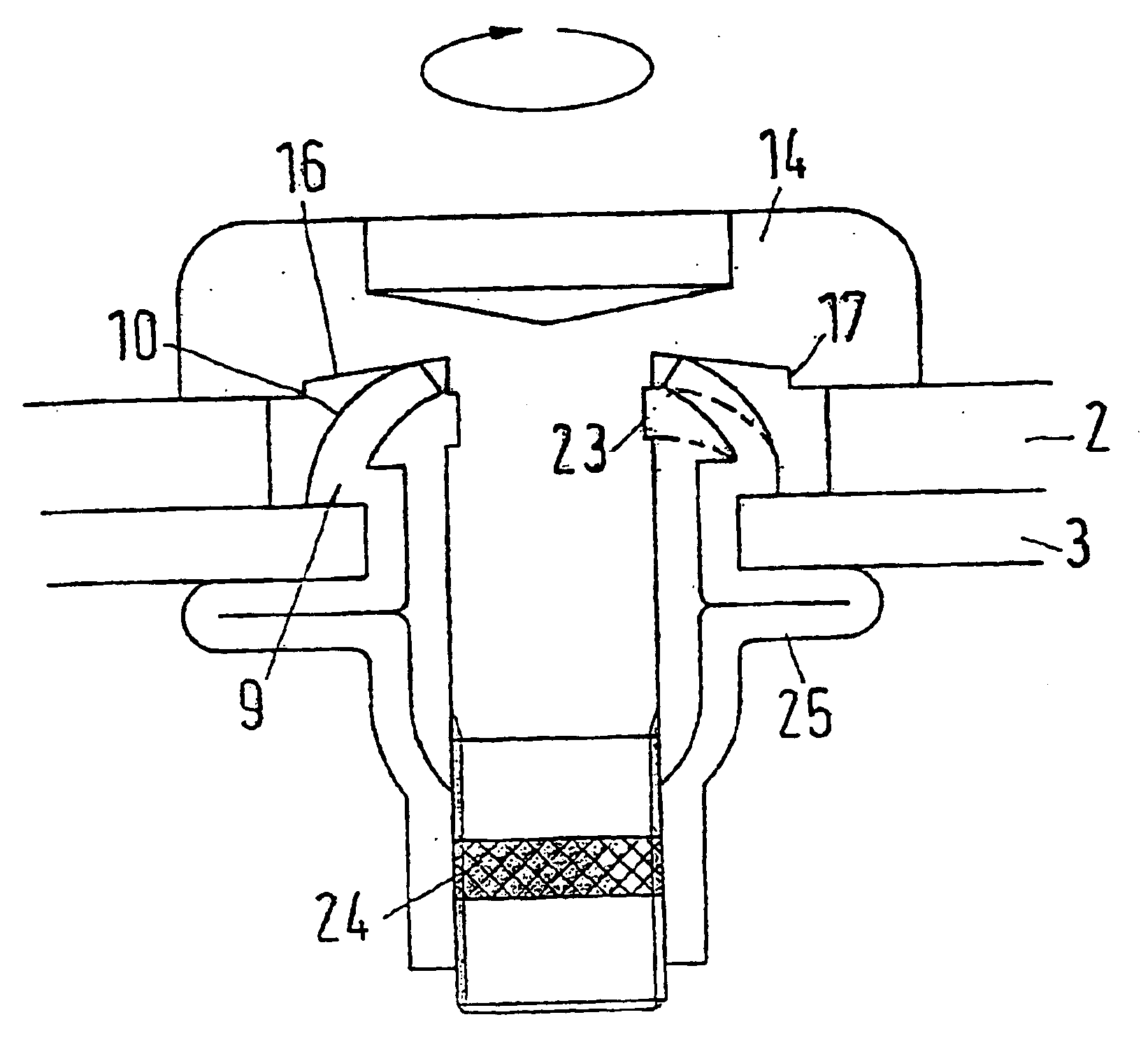
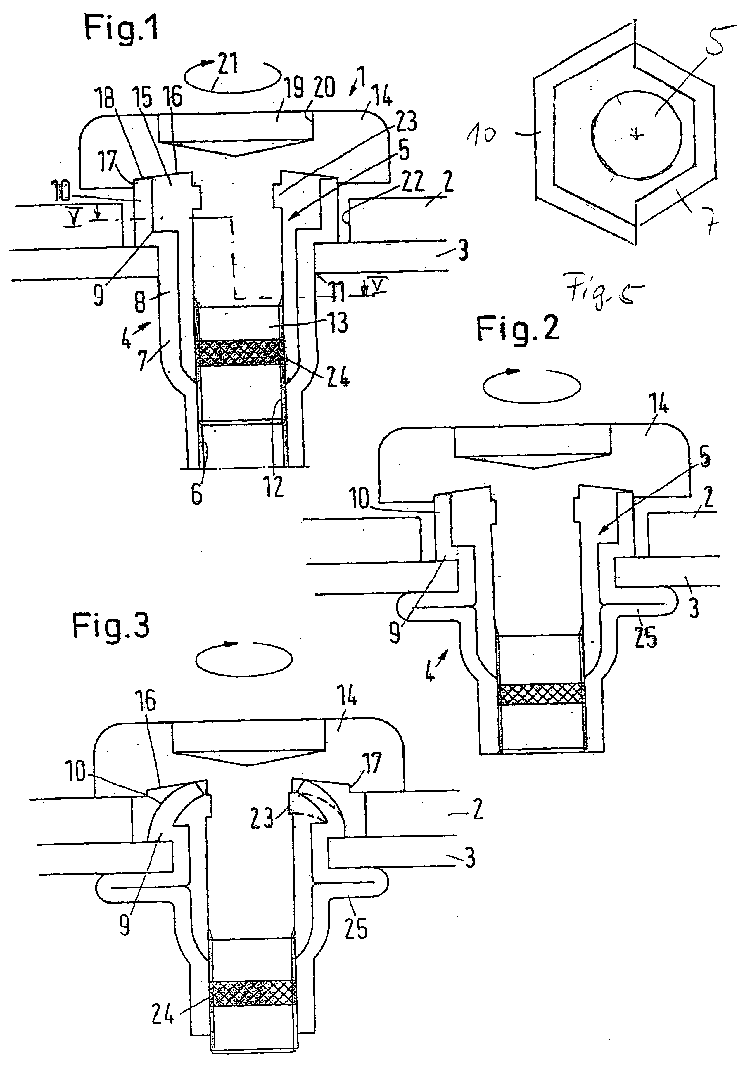
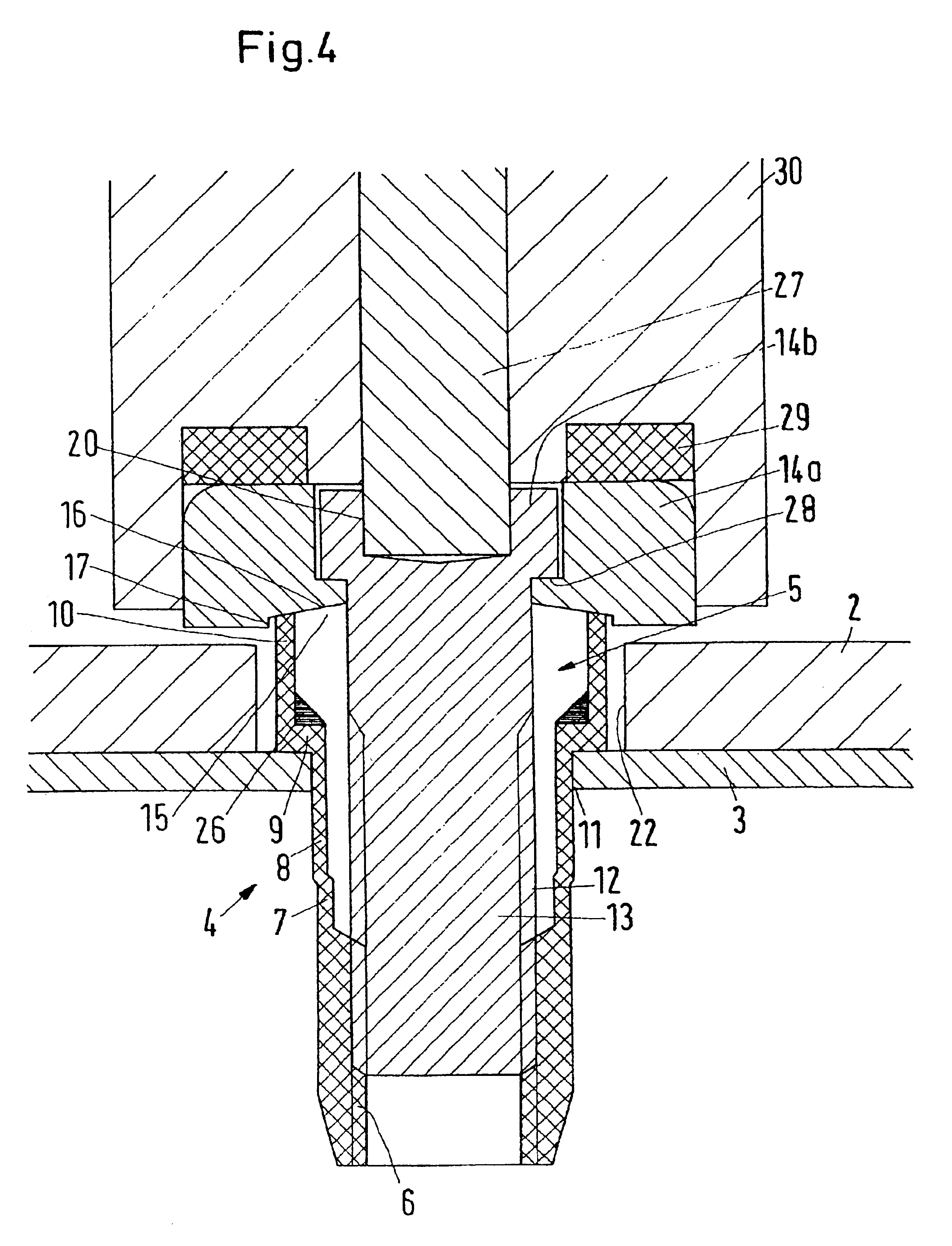
[0014]The new blind rivet nut is ultimately fastened exactly like a conventional blind rivet nut. The shank is passed through an opening formed in the sheet metal and deformed by pulling on the thread in such a way that the deformation zone forms a closing head. Thus, the blind rivet nut is held reliably in the sheet metal. The advantage lies however in that the fastening operation and the setting operation can now be performed in a single work cycle. The blind rivet nut is passed with a fastening bolt through the workpiece to be fastened. The shank of the blind rivet nut is then passed through the opening in the sheet metal. Naturally, the fastening bolt can also be introduced after the blind rivet nut has already been inserted in the sheet metal. When the fastening bolt is now tightened, on account of the tension which the fastening bolt exerts on the shank via the thread, the deformation zone is thus deformed and forms the closing head in a conventional way. On account of the extension, in this case it is ensured that the set head of the blind rivet nut is pressed against the sheet metal with the necessary force, so that a rivet connection with sufficient strength can be obtained. Due to the fact that the extension is also deformable, it is ensured that the workpiece can be held fast on the sheet metal with the necessary force when the bolt is turned further. Therefore, not only is a reliable fastening of the blind rivet nut in the sheet metal achieved, but also an equally reliable fastening of the workpiece to the sheet metal. This combined operation is performed practically exclusively by turning the fastening bolt in a single operation. This turning can perfectly well be performed with a motor-driven tool, for example a screwing tool which is operated electrically or with compressed air. By monitoring the screwing torques in individual sections, it can also be monitored whether the operation of setting the blind rivet nut, that is, formation of the set head, and fastening of the workpiece are carried out with sufficient force and reliability. The fastening operation is over when both the closing head is formed and the fastening bolt is applied to the workpiece. The deformable extension automatically adapts to the thickness of the component to be fastened. Upon tightening the fastening bolt, fastening of the component to the sheet metal is therefore completed in a single operation. Nevertheless, it is possible to undo the connection again by unscrewing the fastening bolt. In this case, however, the blind rivet nut is not taken out of the sheet metal. Instead, it remains riveted in.
[0025]In this connection, it is preferred that the reinforcement is formed by an inclined chamfer which at least partially fills an angle between the extension and the set head. Making a chamfer of this kind is relatively easy.

Problems solved by technology

A drawback with this solution is that the torque for tightening the bolts is transmitted to the component to be fastened.
Hence, the component to be fastened may possibly turn as well, leading to consequential damage.
Moreover, the part to be fastened is no longer releasable.
But in this case the connection is not releasable.

Method used


Image

  • Blind rivet nut and fastening unit
  • Blind rivet nut and fastening unit
  • Blind rivet nut and fastening unit

Examples


Embodiment Construction

[0046]A fastening unit 1 for fastening a component 2 (also referred to as a “workpiece”) to a sheet metal 3 comprises a blind rivet nut 4 and a bolt 5. “Sheet metal” in this context means not only sheets made of metal, but also correspondingly thin members made of other materials such as plastic, wood or the like, in which a thread is required for making a releasable connection, which sheets, however, are too thin or too weak to allow a thread being produced therein.

[0047]The blind rivet nut 4 comprises an internal thread 6 which is arranged at the lower end of a shank 7. The shank 7 comprises a deformation zone 8 above the internal thread 6. Above the deformation zone 8 the blind rivet nut 4 comprises a set head 9. The set head 9 comprises an extension 10 which extends upwards, that is, is located opposite the side of the set head 9 on which the shank 7 is arranged.

[0048]The direction information “top” and “bottom” refers to the view of the drawings and serves to simplify the descr...


PUM


Abstract

A blind rivet nut has a shank with a thread and a deformation zone. The blind rivet nut has also a set head with a larger outside diameter than that of the shank. The set head has a deformable extension on a side opposite the shank. A fastening unit formed with the blind rivet nut has a bolt having a threaded shank and a bolt head with an outside diameter larger than an outside diameter of the threaded shank and at least as large as an outside diameter of the deformable extension.

Description

BACKGROUND OF THE INVENTION[0001]1. Field of the Invention[0002]The invention concerns a blind rivet nut with a shank comprising a thread and a deformation zone, with a set head having a larger outside diameter than the shank. Further, the invention concerns a fastening unit with a blind rivet nut of this kind.[0003]2. Description of the Related Art[0004]Blind rivet nuts have been tried and tested for fastening tasks in which a screw connection is required in thin-walled materials, for example, sheet metals, in which normally no thread can be cut. The blind rivet nut is in this case fixed in the sheet metal like a blind rivet and, after fastening thereof, provides a thread for a screw connection which thread has sufficient axial length. The blind rivet nut is set normally by screwing a threaded mandrel into the thread of the shank and placing the blind rivet nut in the preformed hole of the sheet metal. By pulling on the threaded mandrel, the deformation zone is deformed and expande...

Claims


Application Information

Patent Timeline
IPC IPC(8): F16B19/04F16B19/10F16B37/04F16B37/06
CPCF16B19/1072F16B37/067Y10S411/969
Inventor WILLE, LOTHAR
Owner GESIPA BLINDNIETTECHNIK GMBH
Learn More