
Manufacturing method of touch sensor film, touch sensor film, and touch panel

a manufacturing method and touch sensor technology, applied in the field of manufacturing methods of touch sensor films, touch sensor films, touch panels, can solve the problems of deterioration of thermal shrinkage of supports, increased absolute value of thermal shrinkage, and decreased rigidity of supports

Active Publication Date: 2017-06-22
FUJIFILM CORP
View PDF2 Cites 6 Cited by
  • Summary
  • Abstract
  • Description
  • Claims
  • Application Information

AI Technical Summary

Benefits of technology

The invention proposes a way to prevent issues with the support of a thin touch sensor film, such as deformation and moire, during manufacturing. By subjecting the support to annealing treatment at a high temperature, the thermal shrinkage of the support is deteriorated, allowing for a low thermal shrinkage treatment that prevents deformation and moire. Additionally, the inventors found that by using multiple pass rollers for roll transportation, streak-like wrinkles can be generated on the support. However, by cooling the support through contact with the rollers and limiting the annealing treatment temperature, the support can be prevented from plastic deformation. Ultimately, this invention provides a better manufacturing method for touch sensor films that can prevent issues with the support.

Problems solved by technology

However, it was found that, even in a case where a mesh electrode was formed on a support of a touch panel using the mesh pattern disclosed in JP2013-214545A, moire occurred due to a deviation of a position of the mesh electrode caused by particularly significant deformation occurring when manufacturing a mesh electrode by performing roll transportation using a thin support.
When a thickness of a support of a touch sensor film is decreased in order to form a thin touch panel, rigidity of the support is decreased according thereto, and accordingly, thermal shrinkage of the support is deteriorated (an absolute value of thermal shrinkage is increased).

Method used


Image

  • Manufacturing method of touch sensor film, touch sensor film, and touch panel
  • Manufacturing method of touch sensor film, touch sensor film, and touch panel
  • Manufacturing method of touch sensor film, touch sensor film, and touch panel

Examples


example 1

[0084]

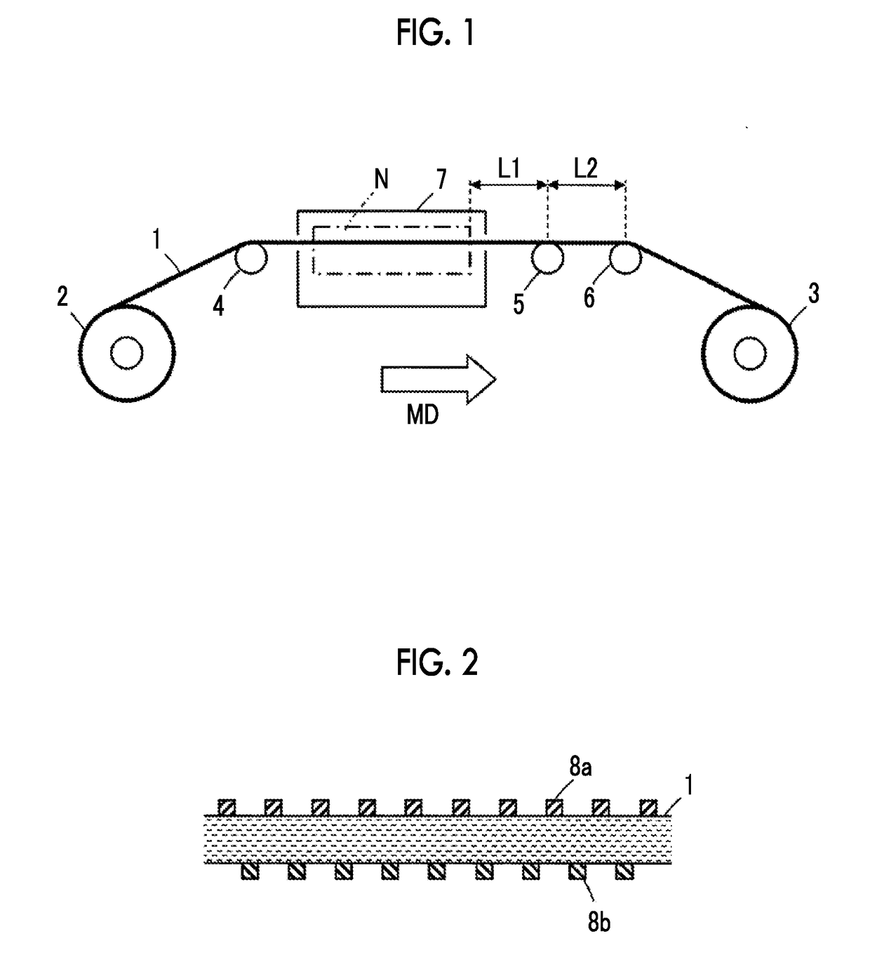
[0085]As the support, an elongated sheet (COSMOSHINE A4300, manufactured by Toyobo Co., Ltd.) which is formed of polyethylene terephthalate (PET), has a dynamic glass transition temperature of 115° C., and has a thickness of 75 μm was used. As shown in FIG. 1, the support was transported and subjected to the annealing treatment by a transportation device in which the delivery roller 2, the pass roller 4 before a drying furnace, the drying furnace (heater) 7, a first pass roller 5 after the drying furnace, and the second pass roller 6 after the drying furnace are sequentially disposed.

[0086]More specifically, the support was subjected to the annealing treatment for 10 seconds to 30 seconds in the drying furnace 7 including the annealing treatment chamber N having an entire length of 16 m set to 150° C. while transporting the support at a rate of 60 m / min. At this time, the support was transported at a tension of 40 N / m in the section between the pass roller 4 and the pass rolle...

example 2

[0134]A touch sensor film was manufactured by the same method as that in Example 1, except for setting the temperature of the drying furnace as 140° C. in the annealing treatment of the support.

example 3

[0135]A touch sensor film was manufactured by the same method as that in Example 1, except for setting the temperature of the drying furnace as 130° C. in the annealing treatment of the support.


PUM


Abstract

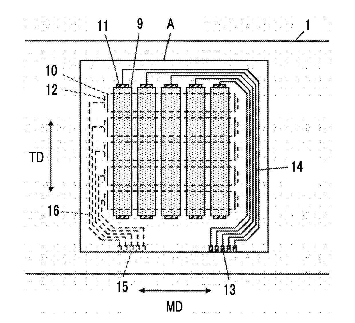
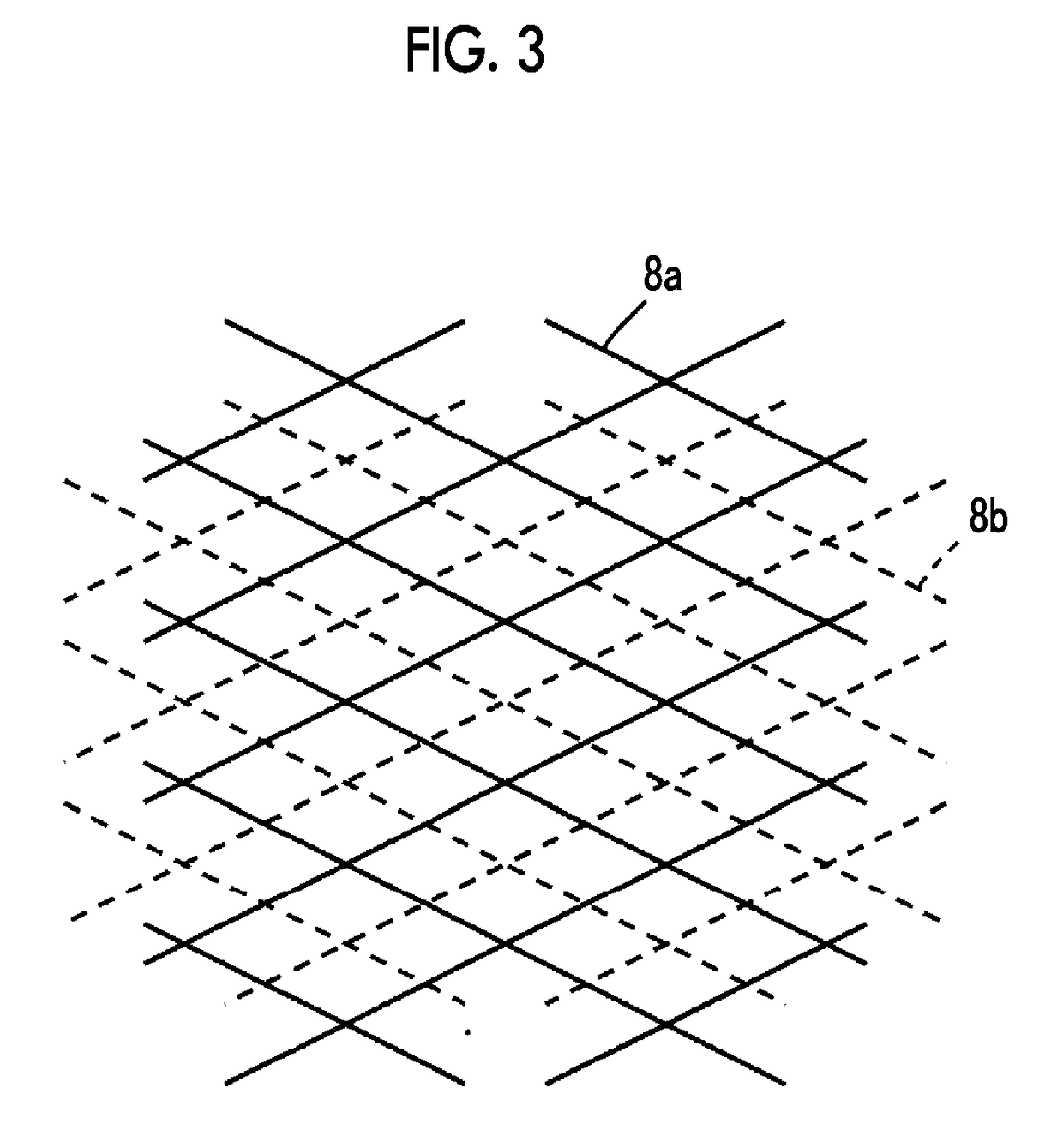
A touch sensor film preventing moire occurring in accordance with deformation of a support is manufactured by performing roll transportation of an elongated transparent support 1 having a thickness smaller than 80 μm using a plurality of pass rollers 4, 5, and 6; performing annealing treatment with respect to the support 1 at a temperature which is equal to or lower than a temperature obtained by adding 35° C. to a dynamic glass transition temperature of the support 1; and forming a mesh pattern formed of thin metal wires 8a on a surface of the support 1 subjected to the annealing treatment.

Description

CROSS-REFERENCE TO RELATED APPLICATIONS[0001]This application is a Continuation of PCT International Application No. PCT / JP2015 / 071659 filed on Jul. 30, 2015, which claims priority under 35 U.S.C. §119(a) to Japanese Patent Application No. 2014-175929 filed on Aug. 29, 2014. The above application is hereby expressly incorporated by reference, in its entirety, into the present application.BACKGROUND OF THE INVENTION[0002]1. Field of the Invention[0003]The present invention relates to a manufacturing method of a touch sensor film, a touch sensor film, and a touch panel, and particularly relates to a manufacturing method of a touch sensor film of forming a mesh pattern formed of thin metal wires on a surface of a support, a touch sensor film, and a touch panel.[0004]2. Description of the Related Art[0005]In recent years, touch panels which are used in combination with display devices such as liquid crystal display devices and perform an input operation to an electronic device by coming...

Claims


Application Information

Patent Timeline
IPC IPC(8): G06F3/044G06F3/041
CPCG06F3/044G06F2203/04103G06F2203/04112G06F3/041G06F3/0412G06F3/0446
Inventor NUKUI, KATSUYUKI
Owner FUJIFILM CORP
Learn More