
Intake manifold having failure controlling features

a technology of failure control and intake manifold, which is applied in the field of intake manifolds, can solve problems such as restricting failure to a focused area, and achieve the effect of improving features

Inactive Publication Date: 2017-06-22
FORD GLOBAL TECH LLC
View PDF2 Cites 13 Cited by
  • Summary
  • Abstract
  • Description
  • Claims
  • Application Information

AI Technical Summary

Benefits of technology

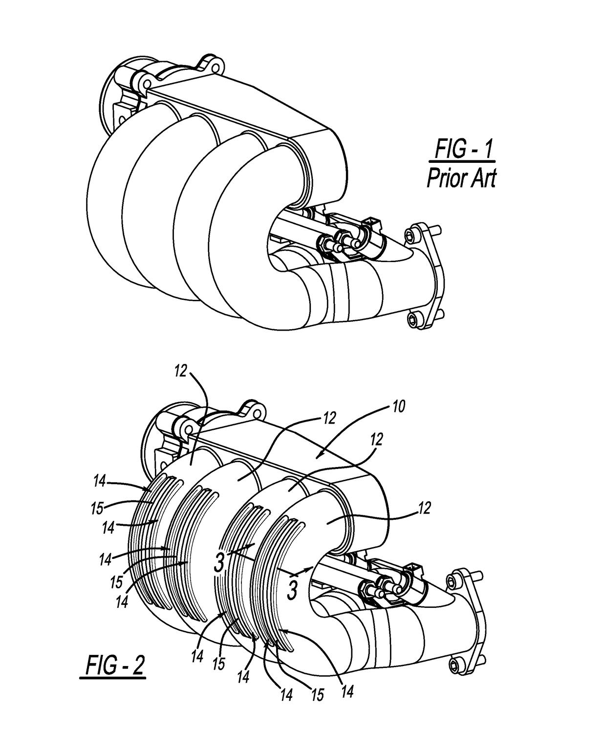
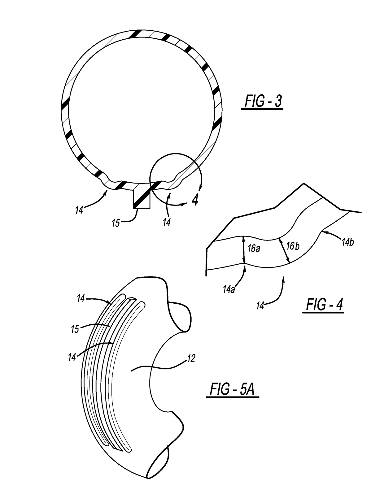
The invention provides an intake manifold with a plurality of runners that have elongated ribs and blisters. These features work together to control how the intake manifold fails during an impact event. The elongated ribs absorb and concentrate the force, while the elongated blisters provide a specific area of intentional failure that directs the force to a specific point on the intake manifold. This design helps to prevent failure of the intake manifold during an impact event.

Problems solved by technology

Specifically, the elongated rib acts to receive and concentrate load while the at least one elongated blister provides an area of intentional failure, thus restricting the failure to a focused area on the intake manifold.

Method used


Image

  • Intake manifold having failure controlling features
  • Intake manifold having failure controlling features
  • Intake manifold having failure controlling features

Examples


Embodiment Construction

[0018]A detailed description of certain preferred embodiments of the present invention is provided in this section. The terminology used herein is for the purpose of describing particular aspects of certain preferred embodiments of the invention, and is not intended to limit the scope of the claimed invention, which will be limited only by the appended claims. The disclosed embodiments are examples of the invention that may be embodied in various and alternative forms. The figures are not necessarily to scale. Some features may be exaggerated or minimized to show details of particular components. The specific structural and functional details disclosed in this application are not to be interpreted as limiting, but merely as a representative basis for teaching one skilled in the art how to practice the invention.

[0019]Unless defined otherwise, all technical and scientific terms used herein have the same meanings as commonly understood by a person skilled in the art to which this inve...


PUM

PropertyMeasurementUnit
thicknessaaaaaaaaaa
lengthaaaaaaaaaa
areaaaaaaaaaaa

Abstract

An intake manifold is provided that comprises a plurality of intake manifold runners 12, and each intake manifold runner comprises at least one elongated rib 15 and at least one elongated blister 14. The elongated rib 15 and the at least one elongated blister 14 operate together to control structural failure of the intake manifold in an impact event. Specifically, the elongated rib acts to receive and concentrate load while the at least one elongated blister provides an area of intentional failure, thus restricting the failure to a focused area on the intake manifold.

Description

FIELD OF THE INVENTION[0001]The present invention generally relates to intake manifolds, and more specifically to intake manifolds having features for receiving and concentrating a load and for providing a focused area of failure during an impact event.BACKGROUND OF THE INVENTION[0002]In an effort to improve passenger safety, modern automobiles employ various means to control component failure during an impact event, such as by absorbing energy. For example, crumple zones, crush cans, and the like are commonly located in the front part of automobiles to absorb energy during a head-on impact event, and they may be found in other parts of the automobile as well.[0003]Intake manifolds having various modifications have been proposed as means for absorbing energy during an impact event. For example, U.S. Pat. No. 5,630,387 discloses an intake manifold that can be broken along fragile zones in order to absorb an impact of a crash. U.S. Pat. No. 7,997,366 discloses an intake manifold that ...

Claims


Application Information

Patent Timeline
Patent Type & Authority Applications(United States)
IPC IPC(8): F02M35/10F02M35/104
CPCF02M35/104F02M35/10242B60K13/02F02M35/10321F02M35/10072B60Y2306/01F02M35/10288F02M35/161B62D21/15
Inventor NOLA, GARYNEWMAN, CHRISTOPHER WILLIAM
Owner FORD GLOBAL TECH LLC
Learn More