
Swivel Mount for Centrifugal Microfluidic Chip

a microfluidic chip and mounting plate technology, applied in fluid controllers, centrifuges, chemistry apparatus and processes, etc., can solve the problems of insufficient force of gravity, and difficulty in controlling movement, and achieve the effect of adding substantial costs

Active Publication Date: 2017-06-22
NAT RES COUNCIL OF CANADA
View PDF0 Cites 5 Cited by
  • Summary
  • Abstract
  • Description
  • Claims
  • Application Information

AI Technical Summary

Benefits of technology

The patent describes a way to control the position of a microfluidic chip in a centrifuge without stopping the centrifuge repeatedly. The chip is mounted on a swivel, which allows for control over the chip's angle of pivot throughout a process. The chip can have multiple chambers, siphon channels, and features that are all affected by the chip's angle of pivot. The guideway in which the chip moves is low friction, and can be designed to have constrictions or higher friction to control the chip's movement. The chip can also have a squiggle motor to further improve control and responsiveness. The swivel mounting with the force applicator allows for passive control of the chip's angular position, and can leverage the centrifugal field to control the chip's position without adding bulk or cost.

Problems solved by technology

Beading can make it difficult to control movement of the microfluid, as it may stay in a centre of a chamber and not approach a desired exit, and the separation of beads leads to uncoordinated movement of the fluid.
Generally the force of gravity is, in itself, insufficient to draw microfluids through microfluidic channels.
This limits materials, adds costs of the treatment to the production of the chips, may preclude some processes or handling of some liquids and, given that such treatments typically last for a limited duration, frequently leads to a host of supply management problems that make such microfluidic chips less commercially attractive.
There are limited fluid movements that can be performed on the chip by using the prior art centrifugal microfluidics.
While numerous protocols have been developed for centrifugal microfluidics, they generally require a lot of human intervention to accomplish some modestly complicated procedures.
These may be complex, heavy, or inaccurate, and control is provided to only a few channels, which results in limited functionality for the chip.
Generally provisioning a chip with an active flow control device to drive fluid in one direction on one channel against the centrifugal field is not cost effective, given the cost of the motor, the added weight to the circuit, and the limited returns avoided by simply requiring the user to stop the chip, prime, or move the chip to a different position, and restart the centrifuge.
Costs of single-use chips with embedded motors may be prohibitive, especially in disposable, single-use chips.
Other techniques involving applying a burst pressure to a valve, or melting a wax plug have other problems too.
Another pragmatically related problem wanting for a solution in this art, is how to effectively lengthen microfluidic chips.
While the accuracy of angular positions of such holders and carriers as taught by Petithory and Kohara may leave something to be desired, and feedback control for ensuring accuracy of positioning is not explained for centrifuges in use, the prior art appears to provide some complex machinery for varying an angular orientation of a microfluidic chip in a plane of a centrifuge, during operation of the centrifuge.
The weight, complexity, durability, and attendant costs of these devices are high.

Method used


Image

  • Swivel Mount for Centrifugal Microfluidic Chip
  • Swivel Mount for Centrifugal Microfluidic Chip
  • Swivel Mount for Centrifugal Microfluidic Chip

Examples


example

[0105]An example of a centripetally operated swivel mount designed with two chip holders coupled by springs, is imaged in FIG. 13. FIGS. 13a-c show the swivel mount having a mass of 50 g mounted on a supporting plate by an axial revolute joint. The two identical coil springs between the chip parts had elastic constant k=83 N / m. FIG. 13a corresponds to a relaxed state of the swivel mount (angle −26°), while b and c show tensioned springs for 0° and 30° rotation angle respectively.

[0106]The swivel mount is formed of a base plate, which is required to support the axial revolute joint, and provides a throughbore for mounting to the centrifuge. The base plate has additional features that provide visual cues for identifying the angular disposition of the chip part, and permits additional chips to be mounted to the base plate. The joints each couple a respective chip part to the base plate, and the two chip parts are coupled by two coil springs. The fabrication of the base plate and chip p...


PUM


Abstract

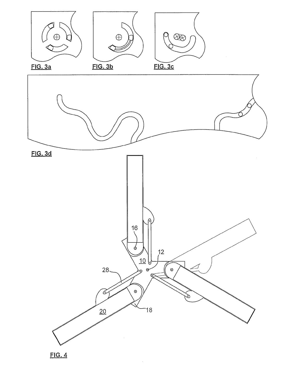
A centrifugal microfluidic chip mounting, kit and method include a swivel joint permitting a chip to rotate about an axis of the chip in a plane swept by a centrifuge, and a force applicator for controlling an angle of the swivel and for applying a force in proportion to a rotational rate of the centrifuge. The mounting includes: a blade part (18) that couples to, or defines, a blade (10) of a centrifuge at a radial distance from a centrifuge axis (12); a chip part (20) that holds the chip at an orientation having a normal not perpendicular to the axis; a one degree of freedom (DoF) joint (16) between the blade part and the chip part; and a force applicator (28) which bears on the chip part at a fixed set of one or more points, which do not surround, and are not surrounded by, the joint.

Description

CROSS-REFERENCE TO RELATED APPLICATION[0001]This application claims benefit from U.S. Provisional Application No. 62 / 002,984 filed on May 26, 2014, which is herein incorporated by reference.FIELD OF THE INVENTION[0002]The present invention relates in general to centrifugal microfluidic devices, and in particular to a microfluidic chip to centrifuge mounting for coupling the chip to a centrifuge, that includes a free swivel joint permitting the chip to rotate about an axis of the chip in a plane swept by the centrifuge, and a force applicator for controlling an angle of the swivel without surrounding or being surrounded by the joint.BACKGROUND OF THE INVENTION[0003]Microfluidic chips, such as labs on chip (LOCs), including micro-Total Analysis Systems (μTAS), are increasingly being used for small volume sample testing in a wide variety of fields, such as medicine, pharmaceutical research, food and water analysis, pathogen detection, security, screening, etc. Many processes (filtratio...

Claims


Application Information

Patent Timeline
IPC IPC(8): B01L9/00B04B5/04
CPCB01L9/527B01L2400/0409B01L2200/025B04B5/0407G01N2035/00495
Inventor CLIME, LIVIUVERES, TEODORMORTON, KEITH
Owner NAT RES COUNCIL OF CANADA
Learn More