Spinning reel rotor and spinning reel

a spinning reel and rotor technology, applied in the field of spinning reel rotors, can solve the problems of increasing the weight of the rotor, concentrating stress on the recess, etc., and achieve the effect of smooth connection, and reliably achieving the stiffness required for the plate-shaped portion

Active Publication Date: 2017-06-15
SHIMANO INC
View PDF0 Cites 0 Cited by
  • Summary
  • Abstract
  • Description
  • Claims
  • Application Information

AI Technical Summary

Benefits of technology

The present rotor design for a spinning reel provides a radially outer part with smaller thickness, which ensures stiffness while simultaneously preventing deformation. The radially inner part is designed such that its thickness gradually decreases outward, allowing for smooth transition between the inner and outer parts. Additionally, the radially outer part includes an annular plate part and a protruding part, which further enhances stiffness and prevents concentration of stress. The plate-shaped portion may also include a rib part or an arm member to increase stiffness without adding weight. Overall, the design ensures optimal performance and durability of the rotor.

Problems solved by technology

Hence, there are also chances of causing a concentration of stress on the recess.
Moreover, there are also chances of an increase in a weight of the rotor.

Method used


Image

  • Spinning reel rotor and spinning reel
  • Spinning reel rotor and spinning reel
  • Spinning reel rotor and spinning reel

Examples


Embodiment Construction

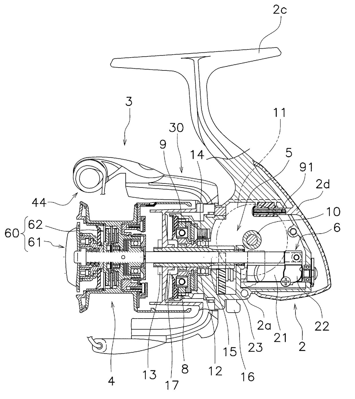
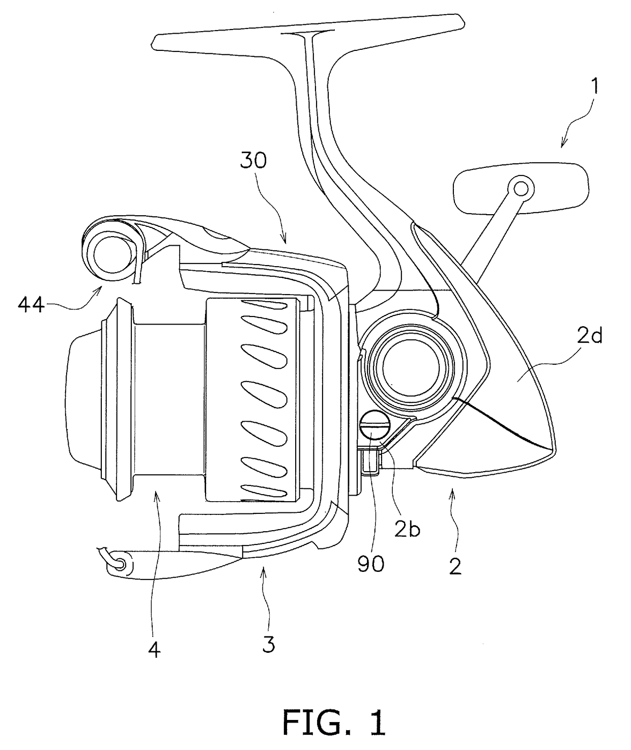
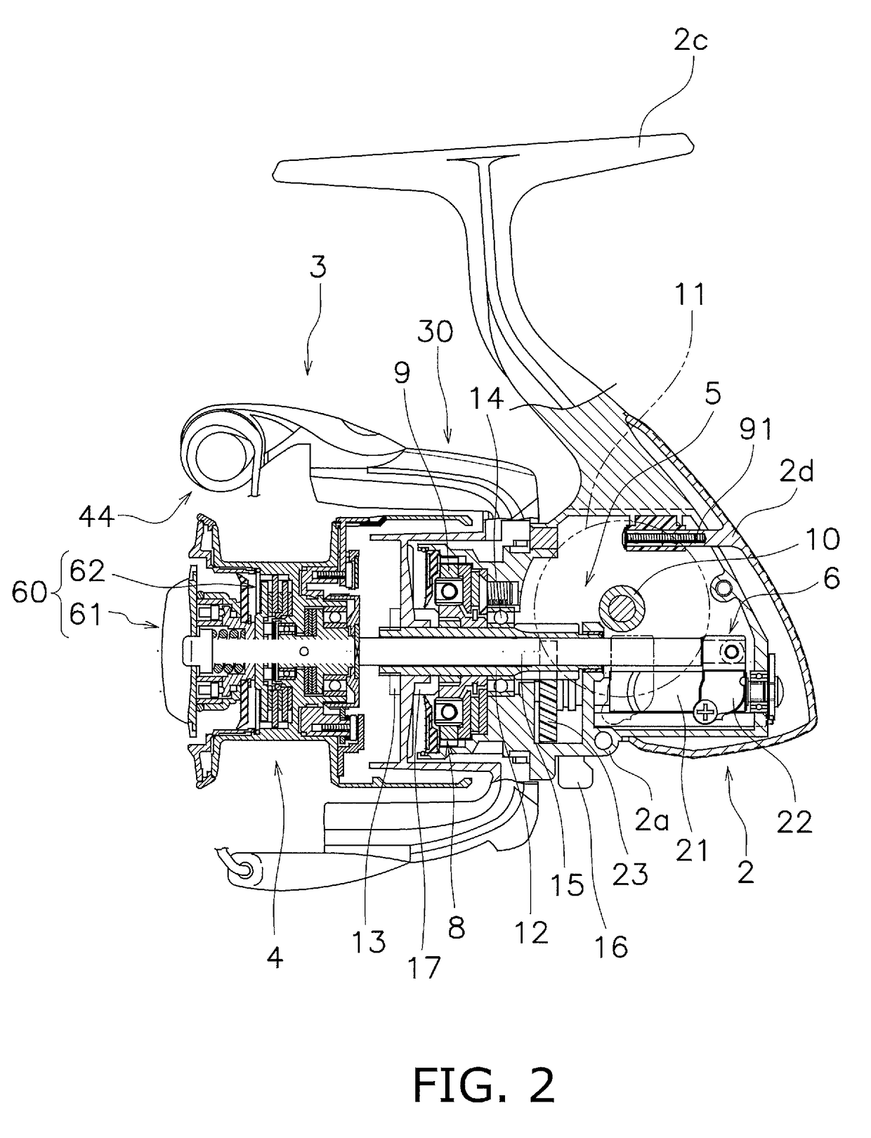
[0027]FIGS. 1 and 2 show a spinning reel employing a preferred embodiment of the present disclosure.

[0028]An extending direction of a spool shaft 15 will be hereinafter referred to as an “axial direction”. The term “axial direction” encompasses directions arranged along the spool shaft 15. It should be noted that when indicating a direction in which a fishing line is reeled out, the “axial direction” will be referred to as a “forward (front) direction” on an as-needed basis. On the other hand, when indicating the opposite direction to a “forward (front) direction”, the “axial direction” will be referred to as a “rearward (rear) direction” on an as-needed basis.

[0029]Additionally, a direction separating from the spool shaft 15 will be referred to as a “radial direction”. When herein indicating a direction approaching to a fishing rod (not shown in the drawing) from the spool shaft 15 in a condition that a reel unit 2 is mounted to the fishing rod, the “radial direction” will be refer...


PUM


Abstract

A rotor for a spinning reel is configured to rotate about a spool shaft, and includes a tubular portion and a plate-shaped portion. The tubular portion is disposed away from the spool shaft at a predetermined interval. The plate-shaped portion includes a radially outer part and a radially inner part. The radially outer part is integrated with an inner peripheral part of the tubular portion. The radially inner part extends from the radially outer part toward the spool shaft. The radially outer part has a smaller thickness than at least a part of the radially inner part.

Description

CROSS-REFERENCE TO RELATED APPLICATIONS[0001]This application claims priority to Japanese Patent Application No. 2015-243200 filed on Dec. 14, 2015, the entirety of which is hereby incorporated by reference in its entirety.BACKGROUND[0002]Technical Field[0003]The present disclosure relates to a rotor for a spinning reel, and particularly to a spinning reel rotor that rotates about a spool shaft. Additionally, the present disclosure relates to a spinning reel, particularly to a spinning reel including the aforementioned rotor.[0004]Background Information[0005]A well-known rotor for a spinning reel rotates about a spool shaft (see e.g., Japan Laid-open Patent Application Publication No. 2013-202006). The spinning reel rotor includes a tubular portion, a pair of rotor arms and a plate-shaped portion. The tubular part is disposed away from the spool shaft at a predetermined interval. One end of each of the rotor arms is integrated with the outer peripheral part of the tubular portion. T...

Claims


Application Information

Patent Timeline
Patent Type & Authority Applications(United States)
IPC IPC(8): A01K89/01
CPCA01K89/0108A01K89/00A01K89/01A01K89/0111A01K97/00
Inventor IKEBUKURO, SATOSHI
Owner SHIMANO INC
Why Eureka
Try Eureka