
Circuit device, oscillator, electronic apparatus, and moving object

a technology of circuit devices and oscillators, applied in the direction of oscillator generators, digital-analog convertors, instruments, etc., can solve the problems of inefficient a/d conversion and achieve the effect of minimizing defects and efficient a/d conversion

Active Publication Date: 2017-06-08
SEIKO EPSON CORP
View PDF4 Cites 4 Cited by
  • Summary
  • Abstract
  • Description
  • Claims
  • Application Information

AI Technical Summary

Benefits of technology

The present patent aims to provide a circuit device, an oscillator, an electronic apparatus, and a moving object that can efficiently perform A / D conversion while minimizing defects caused by rapid changes in temperature detection data. The invention determines a value that changes within a certain range of time from temperature detection data at the previous output timing to be the temperature detection data at a predetermined output timing. This reduces the impact of changes in temperature detection data and helps minimize defects caused by them. The result data is updated based on a comparison result, ensuring accurate temperature detection data.

Problems solved by technology

If A / D conversion result data as a result of A / D conversion greatly changes in a short period of time, a problem may occur.
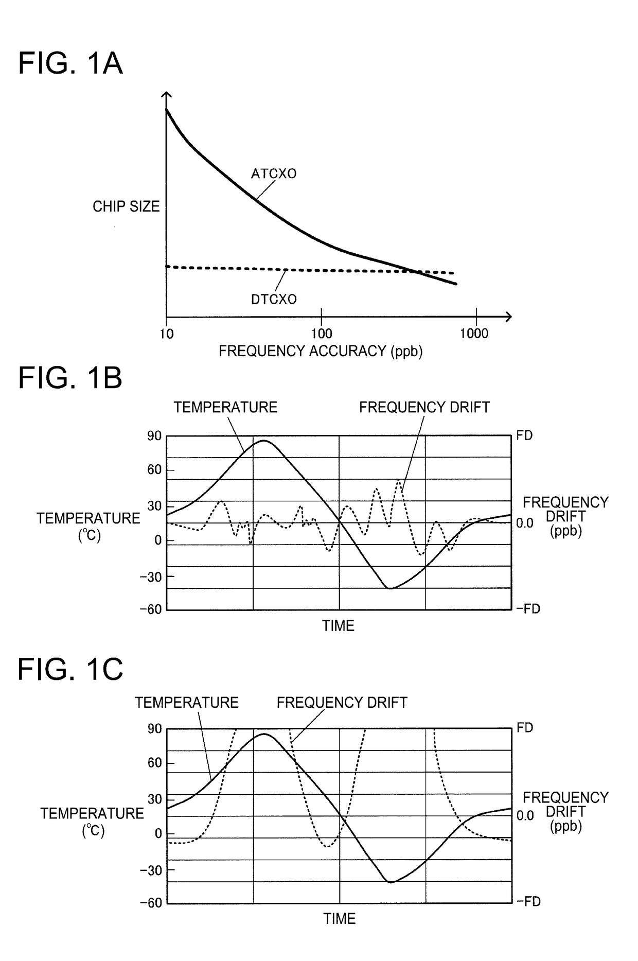
For example, in a digital type oscillator such as a DTCXO, if a frequency drift of an oscillation frequency caused by a temperature change exceeds, for example, an allowable frequency drift range, it has been proved that various problems occur in an apparatus using an oscillation signal of the oscillator.
However, in the technique of the related art disclosed in JP-A-2011-223404 or JP-A-64-82809, none of the above-described content is taken into consideration, and inefficient A / D conversion is performed as a result of permitting a great change in temperature detection data or not taking into consideration the natural condition.

Method used


Image

  • Circuit device, oscillator, electronic apparatus, and moving object
  • Circuit device, oscillator, electronic apparatus, and moving object
  • Circuit device, oscillator, electronic apparatus, and moving object

Examples


modification examples

5. Modification Examples

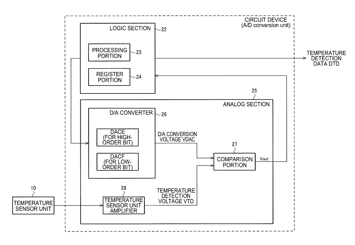
[0239]Next, various modification examples of the present embodiment will be described. FIG. 21 illustrates a configuration example of a circuit device according to a modification example of the present embodiment. The circuit device illustrated in FIG. 21 includes an A / D conversion unit 20 which performs A / D conversion on temperature detection voltage VTD from a temperature sensor unit 10 so as to output temperature detection data DTD, a digital signal processing unit 50 which performs a temperature compensation process on an oscillation frequency on the basis of the temperature detection data DTD, so as to output frequency control data DDS of the oscillation frequency, and an oscillation signal generation circuit 140.

[0240]In a case where a temperature changes from a first temperature to a second temperature, the digital signal processing unit 50 outputs the frequency control data DDS which changes in the unit of k′×LSB from first data corresponding to the f...


PUM


Abstract

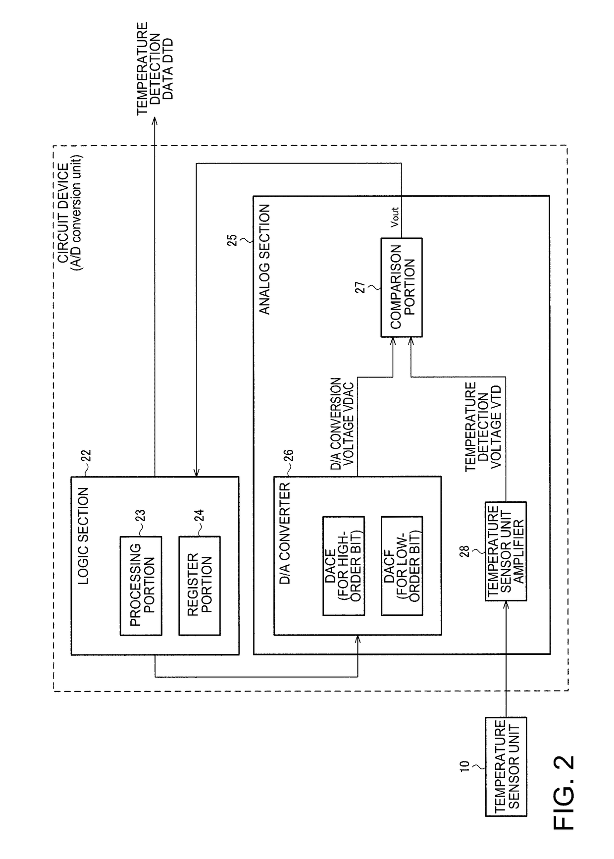
A circuit device includes a D / A converter, a comparator that compares a temperature detection voltage from a temperature sensor unit with a D / A conversion voltage from the D / A converter, and a processing circuit that executes a determination process based on a comparison result from the comparator, and obtains temperature detection data as a result of A / D conversion of the temperature detection voltage, in which, the processing circuit determines the temperature detection data so that a change in the temperature detection data at a second output timing following a first output timing with respect to the temperature detection data at the first output timing is equal to or less than k×LSB.

Description

BACKGROUND[0001]1. Technical Field[0002]The present disclosure relates to a circuit device, an oscillator, an electronic apparatus, and a moving object.[0003]2. Related Art[0004]In the related art, an A / D conversion circuit which performs analog-digital conversion (hereinafter, referred to as A / D conversion) for converting an analog signal to digital data is widely known. As types of A / D conversion circuit, there are various types such as a flash type, a successive comparison type, and a ΔΣ type. For example, JP-A-2011-223404 discloses a method of performing successive comparison type A / D conversion.[0005]There are various circuits using temperature detection data which is a result of A / D conversion of a temperature detection signal (analog signal) from a temperature sensor unit. For example, in the related art, a temperature compensated crystal oscillator (TCXO) is known. The TCXO is used as, for example, a reference signal source or the like in portable communication terminals, GP...

Claims


Application Information

Patent Timeline
Patent Type & Authority Applications(United States)
IPC IPC(8): H03L1/02H03B5/24H03B5/36H03M1/66H03M1/46
CPCH03L1/026H03M1/66H03B5/24H03B5/362H03M1/46H03M1/089
Inventor KANO, SHINNOSUKE
Owner SEIKO EPSON CORP
Learn More