High-definition particle detection during centrifugation

a particle detection and high-definition technology, applied in the direction of centrifuges, instruments, testing medicinal preparations, etc., can solve the problems of difficult to distinguish particles from surface defects on containers, and achieve the effect of preventing blurring of particle images, facilitating identification, and facilitating easy identification

Inactive Publication Date: 2017-06-01
ZEBRASCI
View PDF12 Cites 5 Cited by
  • Summary
  • Abstract
  • Description
  • Claims
  • Application Information

AI Technical Summary

Benefits of technology

[0007]The optical device and imaging sensor are connected to the motor so that when the motor spins both the optical device and imaging sensor spin at the same rpm around the container. The imaging sensor images the static and/or dynamic behavior of the particles in the pharmaceutical liquid within the container during the application of the centrifugal force. In one variation of the system and method, a mechanism can be added for changing the angle of the container with respect to the motor during centrifugation (i.e. tilting the container during rotation/spinning). This allows for control of the orientation of the inner-wall in relation to the axis of rotation. One could make the particles travel up or down the container by tilting the container outward or inward, respectively. This mechanism is useful because while one may be able to view the particles in high definition, it may be difficult to differentiate the particles from surface defects on the container. Manipulating the position of the particles by tilting would be undeniable proof one is observing free-floating particles.
[0008]In the present invention it is shown that moderate centrifugation of fluid containers (up to 2000 RPM) drives particles to the interior surface of the container if the particles are denser than the encompassing fluid (usually an aqueous solution) and to the middle of the container if the particles are less dense tha

Problems solved by technology

This mechanism is useful because while one may be able to view the particles in high definiti

Method used


Image

  • High-definition particle detection during centrifugation
  • High-definition particle detection during centrifugation
  • High-definition particle detection during centrifugation

Examples


Embodiment Construction

Variable-Angle Centrifuge Microscope Images Using Particle Tracking

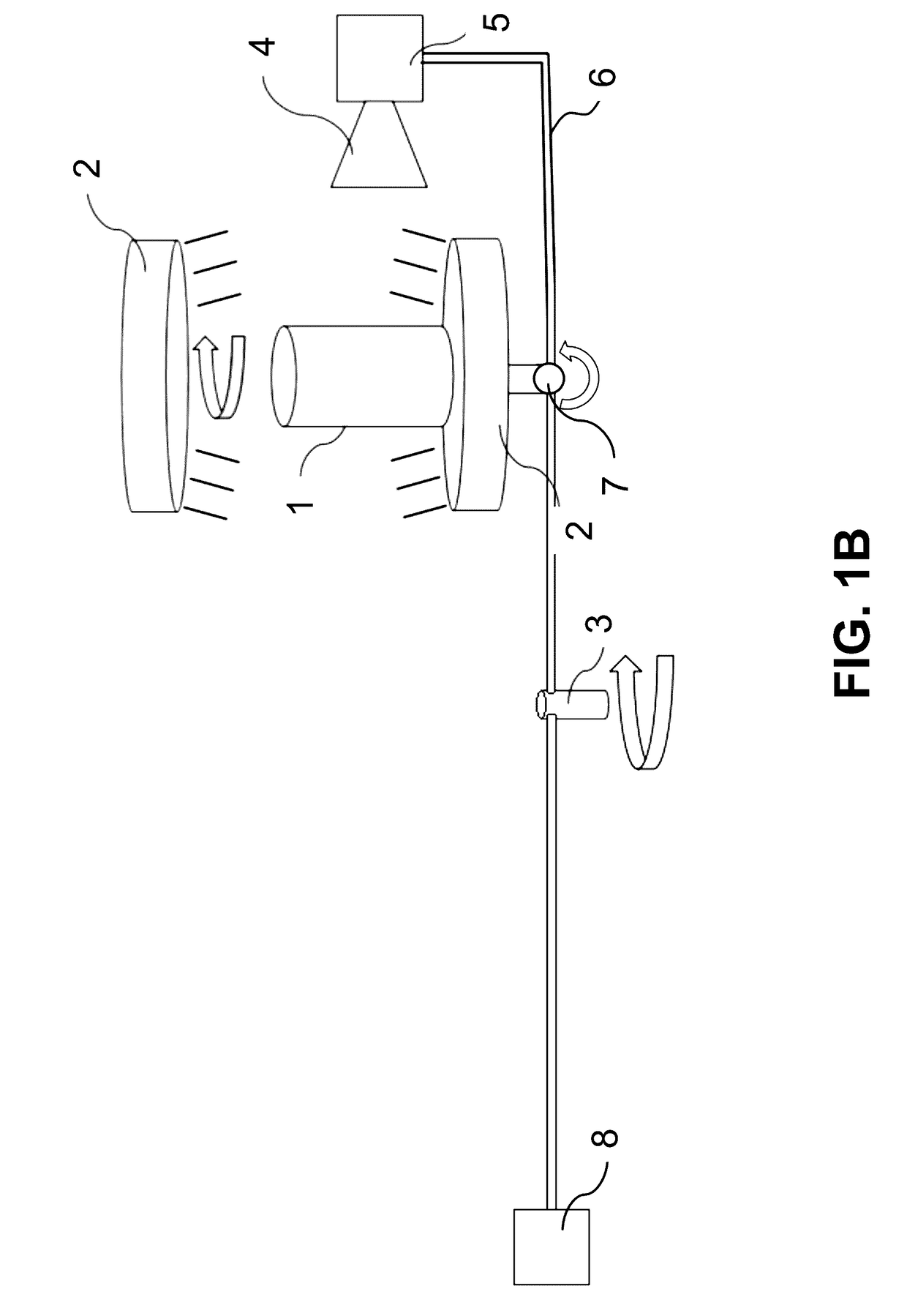
[0020]In this invention, we use a microscope for analyzing free-floating particulate matter in primary containers during active centrifugation. Unlike traditional particle detection systems, which perform inspection after agitating a container, the system described herein performs inspection during centrifugation. This applies a centrifugal force to the container, which pushes free-floating particulate matter to the outer wall of the container. Image sequences are then captured at timed intervals to inspect free-floating particles rendered stationary against the container inner wall due to the centrifugal force.

[0021]Unlike US2014 / 0177932, in the present invention image capture and analysis is performed during centrifugation, rather than after. This applies a completely different dynamic to free-floating particulate matter:[0022]The magnification of optics used in spin and brake inspection systems are often limited b...


PUM


Abstract

High-definition particle detection during centrifugation of a pharmaceutical liquid is provided. Centrifugation of fluid containers drives particles to the interior surface of the container if the particles are denser than the fluid and to the middle of the container if the particles are less dense than the fluid. The imager can then be focused directly on the particle itself for rapid identification without the need for computing complex particle trajectories. If the centrifugation of the container is carried out at an angle to the axis of symmetry of the container, particles can be driven to a single line on the interior surface of the container by the centrifugal force, making the identification of the particles even more straightforward than in two dimensions. The particle imager can also be attached to the rotating container to prevent blurring of the particle image due to the relative motion of the container and imager.

Description

CROSS-REFERENCE TO RELATED APPLICATIONS[0001]This application claims priority from U.S. Provisional Patent Application 62 / 261,847 filed Dec. 1, 2015, which is incorporated herein by reference.FIELD OF THE INVENTION[0002]This invention relates to particle detection methods and systems during centrifugation.BACKGROUND OF THE INVENTION[0003]It is important to identify and characterize different types of particles, which may be present as impurities in a solution, which contains a drug product. Unfortunately, visual inspection cannot detect particles below a certain size (about 100 microns) and in any case is time consuming when dealing with large numbers (millions) of containers.[0004]Hence automated inspection systems such as the one described in the Amgen patent application (US2014 / 0177932) have been developed. In the Amgen system, which includes computer tracking software and imaging hardware, once the imager identifies a particle, a complex computer program estimates the particle t...

Claims


Application Information

Patent Timeline
IPC IPC(8): G02B21/00B04B13/00G01N33/15G02B21/06G02B21/36
CPCG02B21/0016G02B21/06G02B21/361B04B2013/006G02B21/365G01N33/15B04B13/00G02B21/362G02B21/367G01N2015/045G01N2015/0053G01N15/1459G01N15/1463G03B39/00
Inventor NGUYEN, HOANG THANHNOOLANDI, JAANSCHULTHEIS, ROBERT JAMES
Owner ZEBRASCI
Why Eureka
Try Eureka