
Control member with electronic evaluation of the haptic feedback

a technology of haptic feedback and control member, which is applied in the field of control member, can solve problems such as difficulty in manually measuring this distan

Active Publication Date: 2017-05-18
PREH GMBH
View PDF0 Cites 4 Cited by
  • Summary
  • Abstract
  • Description
  • Claims
  • Application Information

AI Technical Summary

Benefits of technology

The invention relates to an electronic control system for a haptic feedback device. The system includes a measuring circuit that measures the current at the actuator and generates a measuring signal. An evaluation unit applies a measuring voltage to the actuator and measures the current that arises during the test period. This process allows for the determination of the actuator's characteristic value, such as its inductance. The invention enables the adjustment of control voltage and period without interfering with the actuator during operation. The technical effect of the invention is to provide a reliable and efficient control system for haptic feedback devices.

Problems solved by technology

Regularly, there is a problem with such control members with electromagnetic actuators in that the generated haptic feedback, i.e. the strength of the impact or vibration excitation, varies to a great extent depending on the mechanical tolerances, in particular the tolerances relating to the relative orientation of the armature and the coil, possibly of the iron core and the armature, but also depending on the temperature and air humidity.
These changes may be the result of, for example, excessive heating or wear in the mounting or bearing arrangement of the operating part.
At least during operation, manually measuring this distance is difficult.

Method used

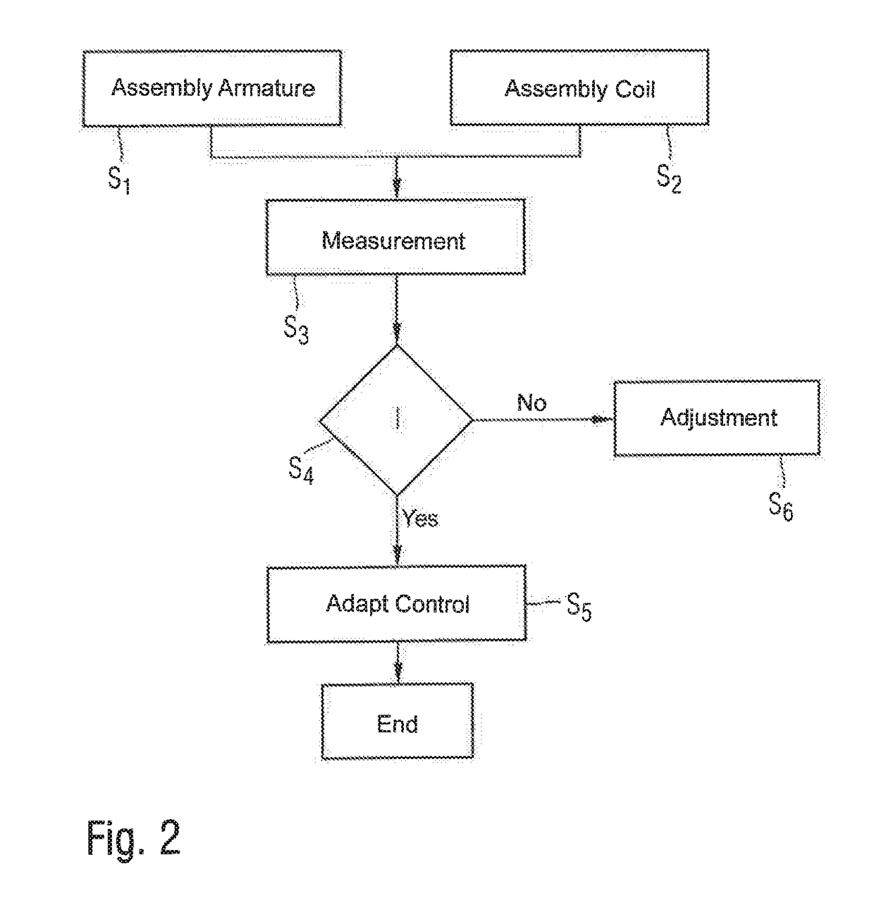

Image

  • Control member with electronic evaluation of the haptic feedback
  • Control member with electronic evaluation of the haptic feedback
  • Control member with electronic evaluation of the haptic feedback

Examples


Embodiment Construction

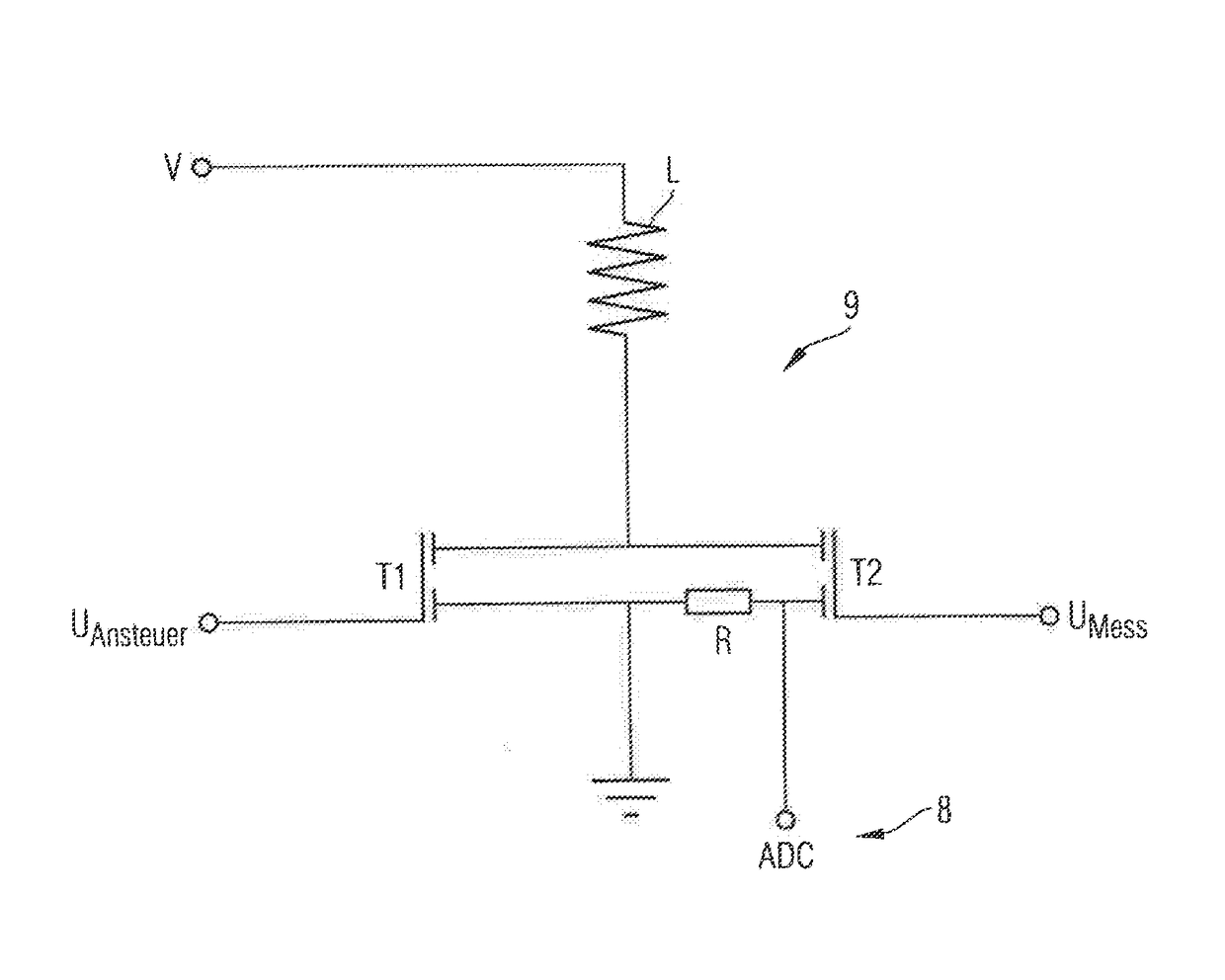
[0046]FIG. 1 shows an embodiment of the assembly according to the invention. It has a control member 1. This control member 1 comprises an operating part 2 defining an operating surface 11 on a surface facing towards the operator. The operating part 2 is movably supported relative to a carrier 5. Furthermore, returning means 10 in the form of springs are provided between the carrier 5 and the operating part 2 in order to cause an elastic return of the operating part 2 into a rest position shown in FIG. 1. Furthermore, an electromagnetic actuator 12 is provided in order to drive the operating part 2 from the rest position, counteracting the operative direction of the returning means. The electromagnetic actuator 12 has a coil 6 on the side of the carrier made from an electrical conductor and a preferably ferromagnetic armature 3 on the side of the operating part, between which an air gap is formed. The current-carrying coil 6 cooperates with the armature 3, driving the operating part...


PUM


Abstract

An assembly consisting of a control member which comprises a carrier, an operating part movably supported on the carrier, an electromagnetic actuator comprising an armature and a coil for driving the operating part movingly relative to the carrier is provided. The assembly further comprises an electronic control system connected in an electrically conductive manner with the electromagnetic actuator for applying a control voltage to the electromagnetic actuator for a predetermined control period in a control step in order to generate a haptic feedback; a measuring circuit connected in an electrically conductive manner to the electromagnetic actuator for measuring a current present at the electromagnetic actor and for generating a measuring signal proportional thereto; and an evaluation unit connected in an electrically conductive manner at least to the measuring circuit and designed, in a measuring step offset in time relative to the control step, to apply a measuring voltage to the electromagnetic actuator by the electronic control system for a predetermined test period shorter than the control period, in order to measure by the measuring circuit the current which arises at the electromagnetic actuator as the test period elapses due to the application of the measuring voltage and to generate a measuring signal proportional thereto, and in order to obtain a characteristic value of the actuator based on the measuring signal.

Description

CROSS-REFERENCE TO RELATED APPLICATION[0001]This application claims foreign priority of German application Serial Numbers DE 10 2015 119 615.8 filed on Nov. 13, 2015 and DE 10 2016 103 766.4 filed on Mar. 2, 2016, the entireties of which are incorporated herein by reference.BACKGROUND OF THE INVENTION[0002]Field of the Invention[0003]The invention relates to a control member comprising: a carrier, an operating part movably supported on the carrier, an electromagnetic actuator comprising an armature and a coil for driving the operating part movingly relative to the carrier, the assembly further comprising an electronic control system connected in an electrically conductive manner with the electromagnetic actuator for applying a control voltage to the electromagnetic actuator for a predetermined control period in a control step in order to generate a haptic feedback.[0004]Description of the Prior Art[0005]Regularly, there is a problem with such control members with electromagnetic act...

Claims


Application Information

Patent Timeline
IPC IPC(8): G05B19/418
CPCG05B2219/31361G05B19/4189F02D41/20F02D2041/202G01B7/14G01R27/26H01F7/1844G06F3/016H01F7/1638H01F2007/1861Y02P90/02
Inventor BODENSTEIN, TOBIAS
Owner PREH GMBH
Learn More