Eureka AIR delivers breakthrough ideas for toughest innovation challenges, trusted by R&D personnel around the world.

Three-Dimensional Prefabricated Flashing Scaffolding System

Active Publication Date: 2017-05-18
NORWOOD ARCHITECTURE INC
View PDF12 Cites 5 Cited by
  • Summary
  • Abstract
  • Description
  • Claims
  • Application Information

AI Technical Summary

Benefits of technology

The patent is about a three-dimensional prefabricated scaffold for use in flashing pre-opened window or door openings in a building. The scaffold is made of a mesh or solid material and has a flange and a return that are connected to each other. The flange and return have a sufficient rigidity to maintain their shape. An adhesive can be used to stick the scaffold to the opening of the structure. The return has drainage ribs on its outer surface and the flange has drip margin. The scaffold can be attached to both the sill / head and jamb returns. It also has a hinged flap connected to the flange. The technical effect of this patent is a pre-fabricated scaffold for easily flashing window or door openings in a building.

Problems solved by technology

In particular, openings have historically suffered from leaks due to defects in the installation of the flashing as well as the inherent difficulty of water / weather-proofing the three dimensional corners of openings with flat or folded strips of flashing.
The flashing can be folded into an opening, but inherent waterproofing problems result where the flat or folded strips meet the corners of the opening.
These fluid applied flashing systems also have significant disadvantages including the propensity of the fluid applied flashing to crack at the corners of the opening as the material dries or is stressed due to thermal movement of the building and openings.
In addition, these fluid applied systems do not include, within the flashing material itself, returns, or back-dams to reduce the infiltration of water and / or air at the opening.

Method used


Image

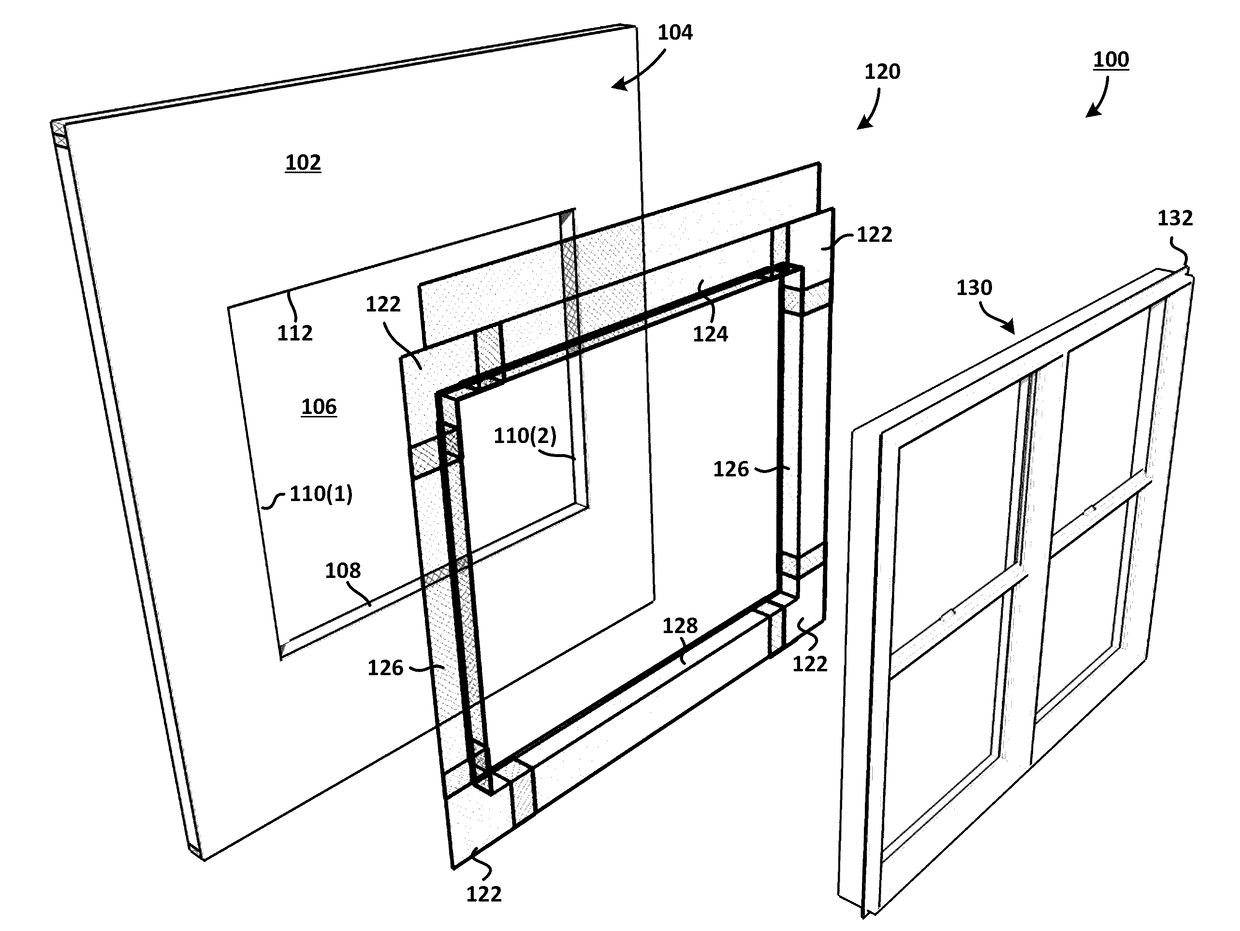
  • Three-Dimensional Prefabricated Flashing Scaffolding System
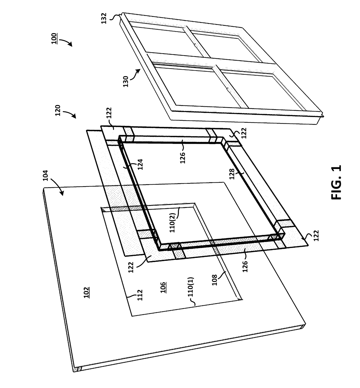
  • Three-Dimensional Prefabricated Flashing Scaffolding System
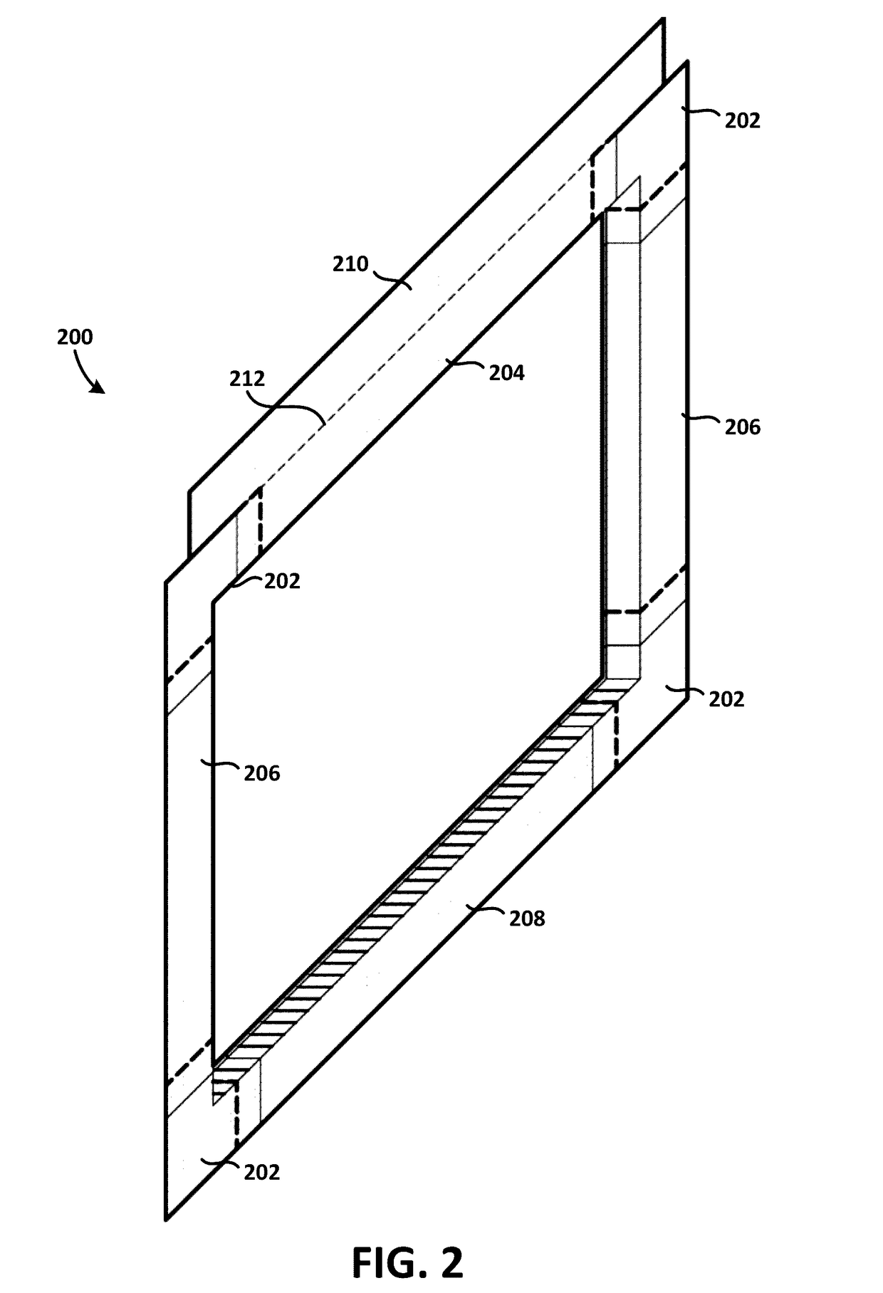
  • Three-Dimensional Prefabricated Flashing Scaffolding System

Examples


Embodiment Construction

[0034]The present disclosure may be understood by reference to the following detailed description taken in conjunction with the drawings briefly described below. It is noted that, for purposes of illustrative clarity, certain elements in the drawings may not be drawn to scale. In particular, the thicknesses of many elements shown in certain drawings herein may be exaggerated in comparison to their height and width. Specific instances of an item may be referred to by use of a numeral in parentheses (e.g., jamb 110(1), 110(2), etc.) while numerals without parentheses refer to any such item (e.g., sill 108).

[0035]Fenestration is an architectural term of art that generally refers to an opening in a surface of a structure. A “fenestration product” as utilized herein is a product that extends through an exterior surface of a structure at a fenestration opening; framed windows, framed doors and skylights are examples of fenestration products.

[0036]Disclosed herein is a three-dimensional pr...


PUM


Abstract

A three dimensional scaffold formed of mesh, or semi-porous material is designed to be inserted into and to surround an opening in the exterior structure of a building to receive a fenestration product such as a door, a vent, a window and a skylight. The three dimensional scaffold is pre-formed into three-dimensional shapes that include corners, returns, back-dams, and optional head flaps that provide a scaffold and backing for the application of a fluid applied water / weather-proofing material. The separate fluid applied waterproofing / weatherproofing may be applied by spray, brush or roll and can be asphalt, rubber, plastic or other fluid applied material. The scaffolding may be formed out of mesh, or other semi-porous fiberglass, metal, plastic, synthetic or other material that can be formed into three dimensional shapes. When combined with a fluid applied weather / waterproofing, the scaffolding provides a superior, continuous, reinforced weather / water-proofing system to protect openings and fenestrations in buildings.

Description

BACKGROUND[0001]Building construction commonly involves flashing and sealing of openings in the exterior surface of a structure, where fenestration products such as windows, doors, skylights, and vents are located, to prevent moisture or air from entering the envelope of the structure. To water / weather-proof such openings, various types of flashing products have been developed which are installed at the openings and surrounding the fenestration products. One such flashing product includes strips of self-adhered flashing often sold in rolls and made of asphalt, rubber or similar materials. These strips of self-adhered flashing are commonly adhered to the sheathing and wrapped into the opening at the framing surface of the opening, or adhered to the sheathing and placed over the edges, “fins,” or frames of the fenestration product. The opening in the exterior of the structure is typically described as having a bottom edge (the sill), a top edge (the head), and the vertical side edges ...

Claims


Application Information

Patent Timeline
IPC IPC(8): E06B1/62E06B7/14E06B1/36
CPCE06B1/36E06B1/62E06B7/14E06B2001/628
Inventor NORWOOD, STEVEN A.
Owner NORWOOD ARCHITECTURE INC
Why Eureka
Eureka Blog
Learn More