In-ear monitor manufacturing process

a manufacturing process and in-ear monitor technology, applied in the field of in-ear monitor manufacturing process, can solve the problems of difficult to design a generic in-ear monitor that can be comfortably inserted into the external ear canal, generic in-ear monitors tend to be shallow in design, and the user's comfort is less

Inactive Publication Date: 2017-05-11
LOGITECH EURO SA
View PDF16 Cites 6 Cited by
  • Summary
  • Abstract
  • Description
  • Claims
  • Application Information

AI Technical Summary

Benefits of technology

[0012]Embodiments of the present disclosure generally relate to a process of forming a custom in-ear monitor that includes capturing a digital anatomical representation of a surface of a body part at a first location, wherein capturing comprises digitally scanning at least a portion of the body part and storing data associated with the captured surface dimensions of the body part in non-volatile memory of a first electronic device, transferring the stored data to a second electronic device positioned at a second location, forming a three-dimensional digital model from the stored data using the second electronic device, transforming the three-dimensional digital model, transferring the transformed three dimensional model to a third electronic device positioned at a third location, forming, at the third location, a body of an in-ear monitor using the transformed three dimensional model, and positioning the acoustic output member and one or more drivers within the formed body, wherein the acoustic output member and one or more drivers reside at least partially within the cavity. The process of transforming the three-dimensional digital model may include altering at least a portion of an external surface of the three-dimensional digital model, and forming a cavity within the three-dimensional digital model, wherein the cavity is sized to receive an acoustic output member and one or more drivers.

Problems solved by technology

Generic in-ear monitors tend to be less comfortable to the user because they do not account for differences in individual ear shape.
Also, without customization, it is very difficult to design a generic in-ear monitor that can be comfortably inserted into the external ear canal.
Therefore, generic in-ear monitors tend to be shallow in design and fit in the outer ear without penetrating the external ear canal.
As a result of the shallow design, there is space between the end of the in-ear monitor and the eardrum, resulting in poor isolation and poor sound quality.
Such a visit may require traveling long distances and waiting extended periods of time for the steps of the process to be completed.

Method used


Image

  • In-ear monitor manufacturing process
  • In-ear monitor manufacturing process
  • In-ear monitor manufacturing process

Examples


process example

Additional Manufacturing Process Example

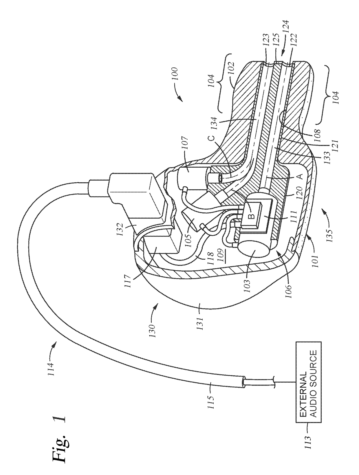
[0045]By eliminating the necessity of tuning each in-ear monitor (IEM) 100 prior to completion of the custom in-ear monitor 100, due to the presence of the optimized and standardized configuration of the acoustic output member 121, embodiments of the present disclosure allow the IEM manufacturing process to be substantially altered from the traditional, more labor intensive processes typically used to manufacture custom-fit IEMs. In one example, the manufacturing process includes after an end user's ear is molded using a conventional wax molding technique to form an ear mold, the ear mold itself is digitally scanned, for example using a three-dimensional (3D) scanner, in order to create a data file that represents the shape of the desired ear mold. The data file is then analyzed and modified to create a final data file that represents the desired external shape as well as the desired internal features that will allow the ear mold to accommodat...


PUM


Abstract

The present disclosure generally provides a method of manufacture of a custom fit in-ear module, including capturing an anatomical representation of a body part at a first location; transferring the stored data to a second electronic device positioned at a second location; forming a three-dimensional digital model from the stored data using the second electronic device; transforming the three-dimensional digital model, wherein the transforming comprises forming a cavity within the three-dimensional digital model, wherein the cavity is sized to receive an acoustic output member and one or more drivers; transferring the transformed three dimensional model to a third electronic device positioned at a third location; forming a body of an in-ear monitor using the transformed three dimensional model; and positioning the acoustic output member and one or more drivers within the formed body, wherein the acoustic output member and one or more drivers reside at least partially within the cavity.

Description

CROSS-REFERENCE TO RELATED APPLICATIONS[0001]This application is a continuation-in-part of application Ser. No. 15 / 275,004, which is an application for reissue of U.S. Pat. No. 9,042,589. This application is hereby incorporated herein by reference.BACKGROUND[0002]Field[0003]Embodiments of the present disclosure generally relate to a process for manufacturing a custom fit in-ear monitor.[0004]BackgroundDESCRIPTION OF THE RELATED ART[0005]In-ear monitors provide an enhanced listening experience for studio recording, stage performance, and audiophile listening. To listen to recorded music, in-ear monitors may be hard-wired or wirelessly connected to a music player to listen to recorded music. For performance or recording of live music, in-ear monitors may be connected directly or wirelessly to a receiver pack worn by the user (e.g., mammal) or connected directly to a transmitter such as a mixer or amplifier.[0006]In-ear monitors are superior to loudspeakers in that they facilitate a pe...

Claims


Application Information

Patent Timeline
Patent Type & Authority Applications(United States)
IPC IPC(8): H04R1/10A61B5/00A61B5/107
CPCH04R1/1016A61B5/1076A61B5/1078H04R2460/15A61B5/6817H04R1/1075A61B2503/12A61B5/1079A61B5/1077H04R1/24H04R2201/105H04R2420/07
Inventor LIU, VINCENTDEPALLENS, PHILLIPPELANSINGER, TODD WILLIAMSAGGIO, JR., JOSEPH A.
Owner LOGITECH EURO SA
Why Eureka
Try Eureka