
Apparatus and method for inspecting a sample using a plurality of charged particle beams

a charged particle and apparatus technology, applied in the direction of electrical apparatus, basic electric elements, electric discharge tubes, etc., can solve the problems of adjusting the excitation of the primary beams, the detector itself, or the placement of the beam separation device,

Active Publication Date: 2017-05-11
TECH UNIV DELFT
View PDF2 Cites 21 Cited by
  • Summary
  • Abstract
  • Description
  • Claims
  • Application Information

AI Technical Summary

Benefits of technology

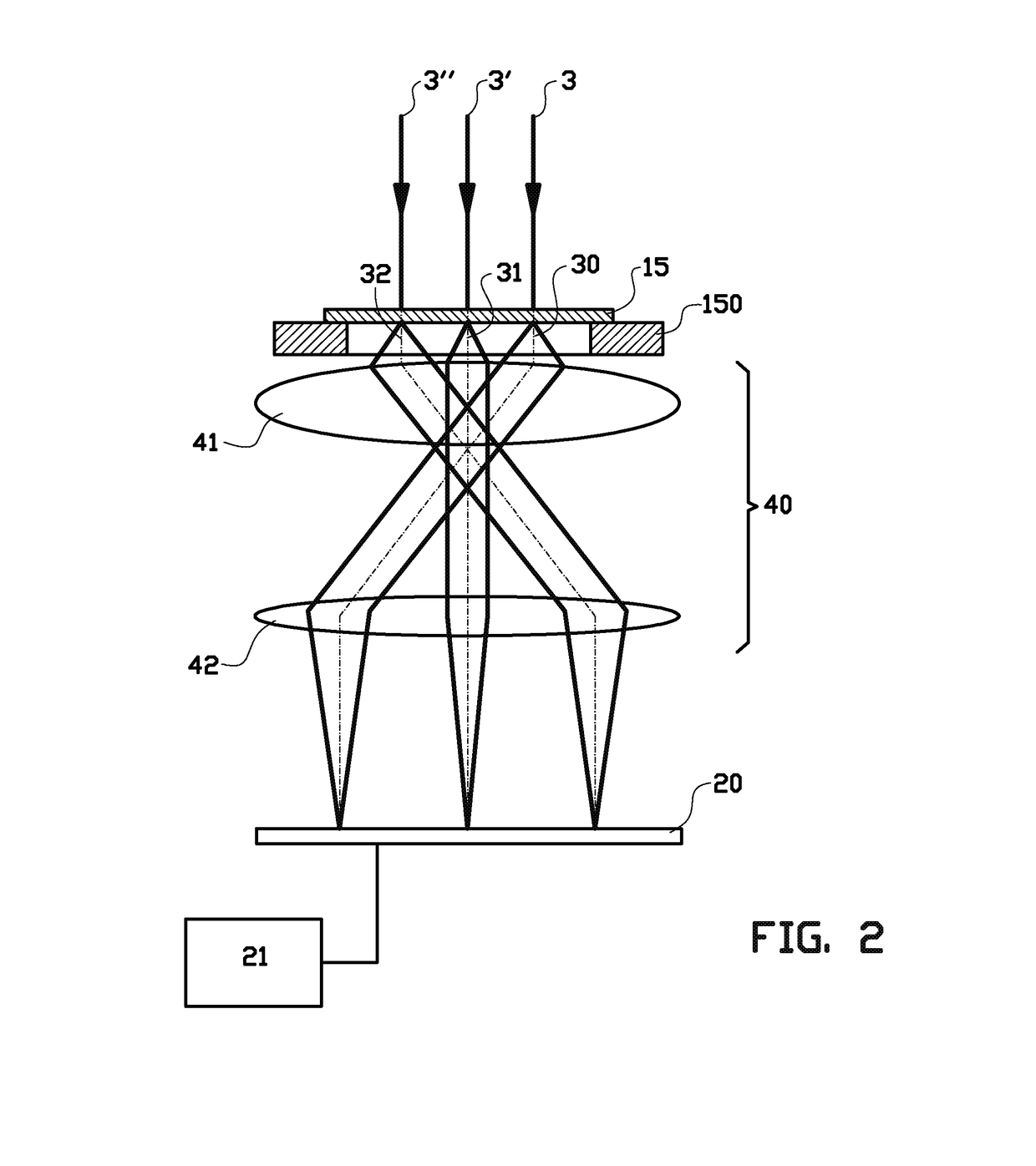
The present invention is an apparatus that can detect photons created by focused primary charged particle beams when they impinge on a sample or after transmission through the sample. Instead of or in addition to detecting a secondary electron signal and / or a backscatter electron signal, the apparatus uses a multi / pixel detector to detect the created photons from two or more focused primary charged particle beams. The optical assembly and multi-pixel detector provide a resolution that enables individual detection of the created photons from two or more adjacent focused primary charged particle beams simultaneously. This detection arrangement offers a new way to analyze samples using focused charged particles. The use of a light transmitting support plate allows for a thin layer of cathodoluminescent material to be used and positions the optical assembly and multi-pixel detector at a side of the support plate facing away from the thin layer of cathodoluminescent material.

Problems solved by technology

A disadvantage of those methods is that either the detector itself, or a beam separation device needs to be placed in the path of the primary electron beams.
Another disadvantage of those methods is that the excitation of the lenses for the primary beams needs to be adjusted in order to accommodate the signal electron beams.

Method used


Image

  • Apparatus and method for inspecting a sample using a plurality of charged particle beams
  • Apparatus and method for inspecting a sample using a plurality of charged particle beams
  • Apparatus and method for inspecting a sample using a plurality of charged particle beams

Examples


first embodiment

[0058]In a first embodiment, the light sensitive area's of the detector 20 is arranged a shown in FIG. 6. Thus for each primary focussed charged particle beam there is a group 60, 60′ of light sensitive area's, also denoted as pixels, comprising:

[0059]a centre light sensitive area 61, 61′ for detecting light generated by the 0th order transmitted charged particles, and

[0060]a ring of light sensitive area's 62, 63, 64, 65, 62′, 63′, 64′, 65′ arranged around the centre light sensitive area 61, 61′ for detecting light generated by the scattered charge particles.

second embodiment

[0061]In a second embodiment, the detector 20 comprises a large number of pixels arranged in rows and columns, which allow to detect any pattern of generated light to be detected. From those pattern, the light generated from the individual primary focused charged particles 3, 3′, 3″ can be distinguished, because this light is arranged in a group of light spots. Each of such a group of light spots comprises a central part which originated from the interaction volume 190 of the 0th order transmitted charged particles, see for example FIG. 5. This central part may be surrounded by light spots which originated from the interaction volume 191 of the scattered charged particles. The signals from these various light spots within the various groups can be separated using appropriated subroutines for reading out and analysing the light signals from the pixels of the detector 20.

[0062]Alternatively, specific pixels or groups of pixels may be allocated or assigned for example according to the ...


PUM


Abstract

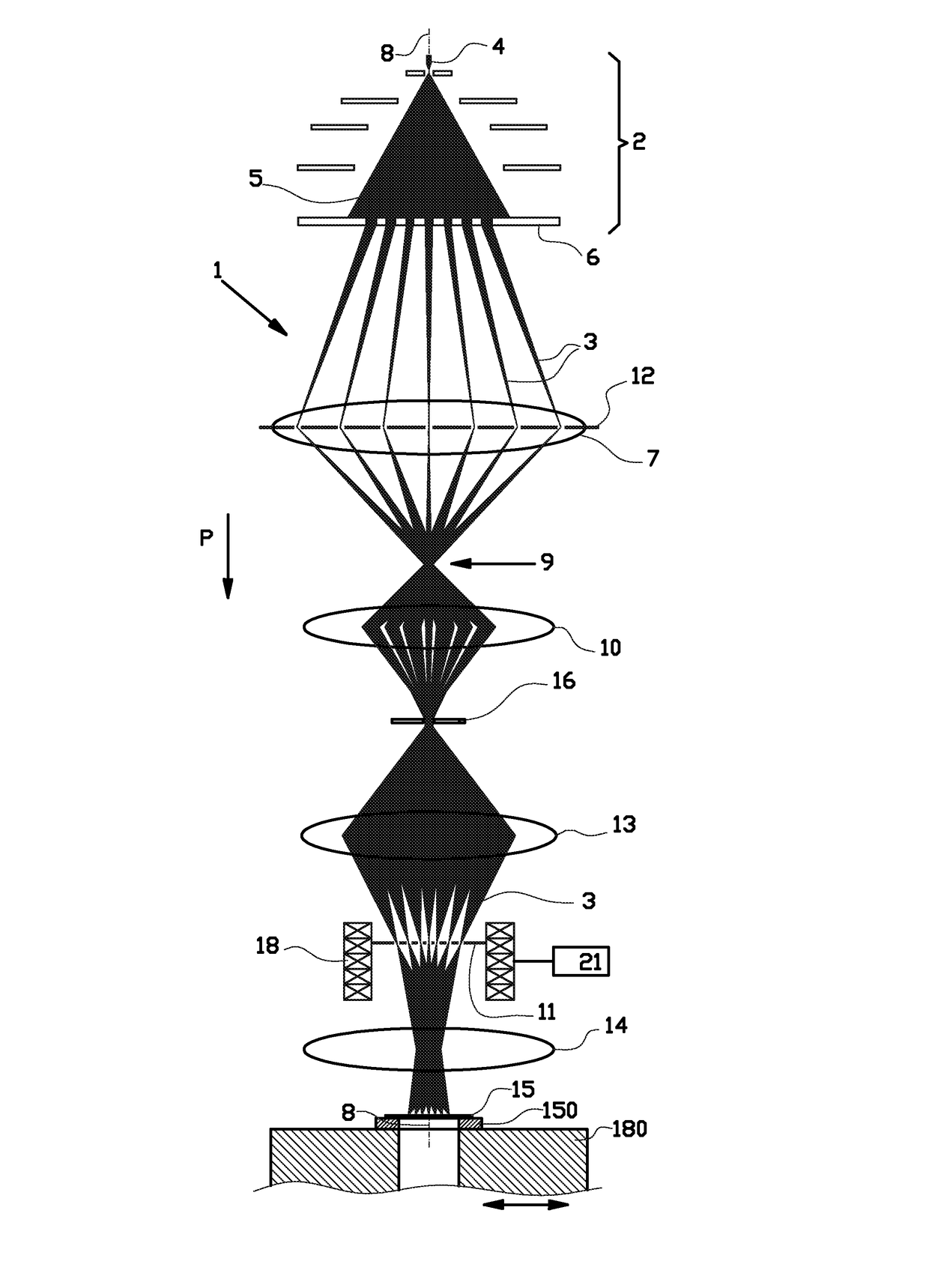
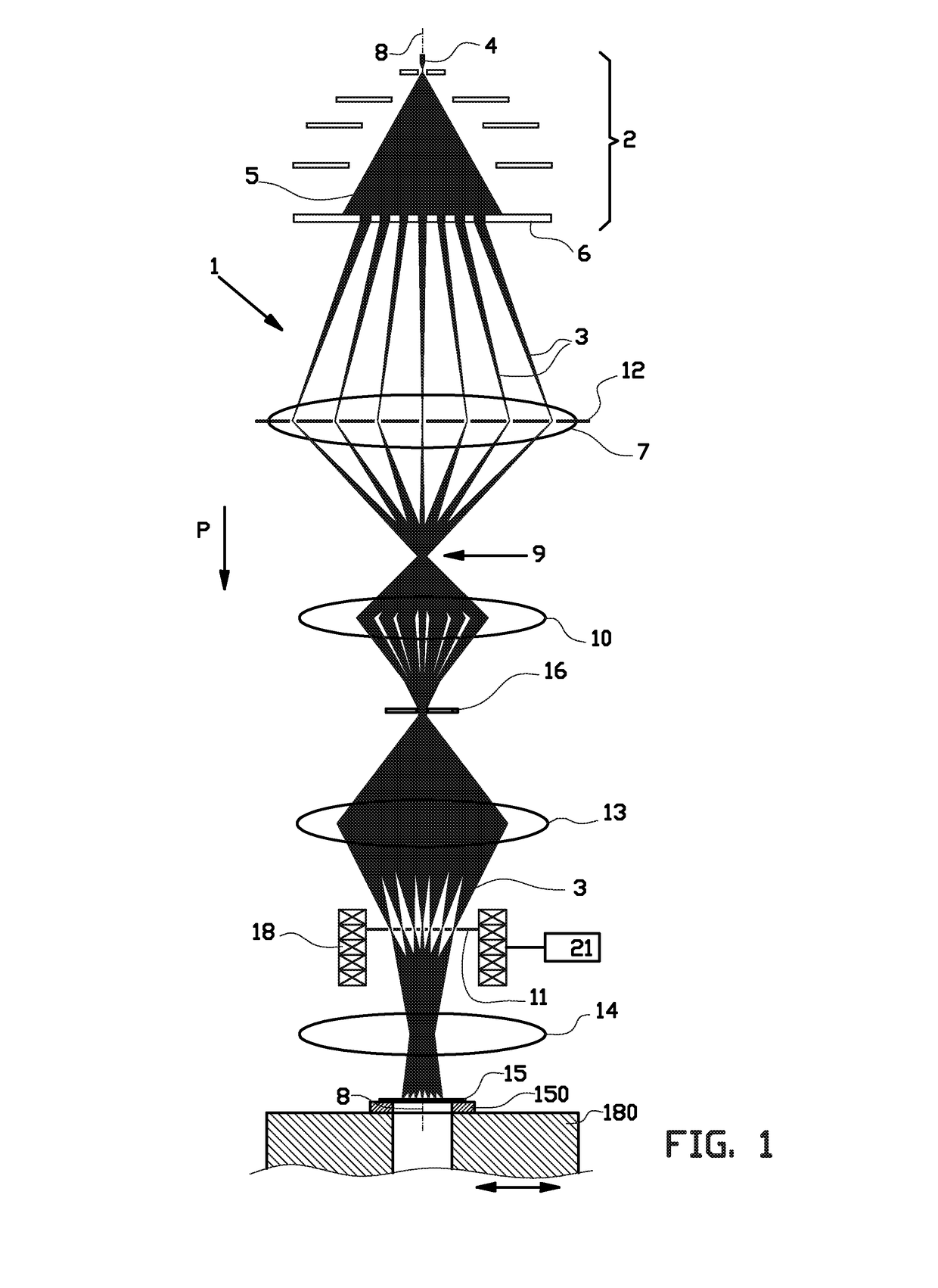
An apparatus for inspecting a sample includes a sample holder for holding the sample; a multi beam charged particle generator for generating an array of primary charged particle beams; an electro-magnetic lens system for directing the array of primary charged particle beams into an array of separate focused primary charged particle beams on the sample; a multi-pixel photon detector arranged for detecting photons created by the focused primary charged particle beams when the primary charged particle beams impinge on the sample or after transmission of said primary charged particle beams through the sample; and an optical assembly for conveying photons created by at least two adjacent focused primary charged particle beams of the array of separate focused primary charged particle beams to distinct and / or separate pixels or to distinct and / or separate groups of pixels of the multi-pixel photon detector.

Description

BACKGROUND[0001]The invention relates to an apparatus and a method for inspecting a thin sample. In particular the invention relates to an apparatus for inspecting a sample using a plurality of charged particle beams, such as a multi-beam scanning electron microscope. The invention may be applied to charged particles of any type, such as electrons, positrons, ions and others.[0002]Such an apparatus is for example disclosed in A.Mohammadi-Gheidari and P.Kruit “Electron optics of multi-beam scanning electron microscope” Nuclear Instruments and Methods in Physics Research A 645 (2011) 60-67. This publication discloses an electron microscope comprising a electron source for generating an array of primary charged particle beams, in particular an array of primary electron beams. These primary electron beams pass an objective lens which directs the electron beams from a common cross-over towards the sample and focuses the primary electron beams into an array of individual spots on the samp...

Claims


Application Information

Patent Timeline
IPC IPC(8): H01J37/28H01J37/22H01J37/244H01J37/141H01J37/20
CPCH01J37/28H01J37/141H01J37/20H01J2237/24495H01J37/222H01J2237/2808H01J37/244H01J2237/2443H01J2237/24455H01J2237/2802H01J37/224
Inventor KRUIT, PIETERZONNEVYLLE, AERNOUT CHRISTIAANREN, YAN
Owner TECH UNIV DELFT
Learn More