
Image processing device and method for detecting image of object to be detected from input data

a technology of image processing and input data, which is applied in the field of image processing device and method for detecting image of object to be detected from input data, can solve the problems of unsatisfactory matching, undetectable detection, and undetectable removal of model features, and achieve the effect of precise detection of objects

Active Publication Date: 2017-05-11
FANUC LTD
View PDF15 Cites 20 Cited by
  • Summary
  • Abstract
  • Description
  • Claims
  • Application Information

AI Technical Summary

Benefits of technology

The technical effect of this patent is to allow for precise detection of objects even if the shapes of the object's edges vary in different images.

Problems solved by technology

However, in practice, it is often the case that an individual of an object used to teach a model pattern or its picture image itself has deviated due to a variation and therefore has not been optimal for matching.
In such a case, expected detection is impossible.
The method disclosed in Japanese Patent No. 5080416 is used to correct a model from information concerning matching at the time of actual detection, but it may undesirably remove a model feature amount in a portion exhibiting large individual differences in shape of an object to be detected, because the portion has a low degree of contribution.
Further, this method may not correct the shape of a model pattern to the one optimal for matching.
However, in this method, when the positions of edges have variations due to the influence of the individual differences or the parallax, the luminance gradient may be low in the average picture image, resulting in inaccurate extraction of edges.

Method used


Image

  • Image processing device and method for detecting image of object to be detected from input data
  • Image processing device and method for detecting image of object to be detected from input data
  • Image processing device and method for detecting image of object to be detected from input data

Examples


first embodiment

[0064]FIG. 4 is a flowchart illustrating processing in the image processing device 21 according to a

[0065]The details of processing performed by the image processing unit 22 in the first embodiment will be described below with reference to FIG. 4.

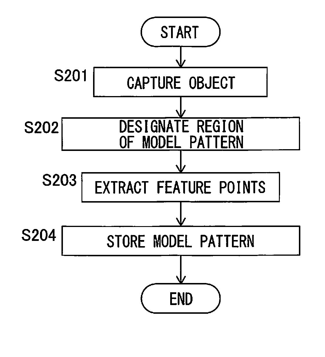
[0066]In step S101, the image processing unit 22 generates a model pattern and stores the generated model pattern in the model pattern storage unit 26.

[0067]The model pattern in this embodiment is formed by a plurality of feature points. Although various points are available as feature points, edge points are used as feature points in this embodiment. Edge points have high luminance gradients in a picture image and may be used to obtain the contour shape of the object 1. Since a method for extracting edge points is described in, e.g., “Computer Vision,” Kyoritsu Shuppan Co., Ltd., January 2007 and is well-known, a description thereof will not be given herein.

[0068]Examples of the physical quantities of an edge point include the position, lu...

second embodiment

[0175]In the second embodiment, even for second feature points which do not correspond to the first feature points of the model pattern, the statistics of the physical quantities of these corresponding points are obtained, and new first feature points are added to the model pattern on the basis of the obtained statistics.

[0176]FIG. 7 is a flowchart illustrating processing according to the second embodiment.

[0177]Steps S301 to S303 are the same as steps S101 to S103 in the first embodiment. With steps S301 to S303, NT_j images of the object have been detected from an input picture image I_j, as in the end of step S103. The detection position of a detected image T_jg (g=1 to NT_j) is defined as R_Tjg.

[0178]In step S304, a corresponding point selection unit 24 selects corresponding points corresponding to first feature points forming the model pattern. Although the process in step S304 is basically the same as that in step S104 of the first embodiment, they are different in that in the...

third embodiment

[0205]A third embodiment will be described next.

[0206]In the third embodiment, on the basis of the statistics of the physical quantities of corresponding points corresponding to a feature point forming a model pattern, determination indices are added to a first feature point forming the model pattern and used in an object detection unit 23 to improve the reliability of detection.

[0207]FIG. 10 is a flowchart illustrating processing according to the third embodiment.

[0208]Steps S401 to S404 are the same as steps S101 to S104 in the first embodiment. NO_i corresponding points determined to correspond to the i-th first feature point P_i forming the model pattern have been found, as in the end of step S104. The m-th corresponding point corresponding to the i-th first feature point P_i of the model pattern is defined as O_im (m=1 to NO_i).

[0209]In step S405, the statistics of the physical quantities of the NO_i corresponding points O_im corresponding to the first feature point P_i are cal...


PUM


Abstract

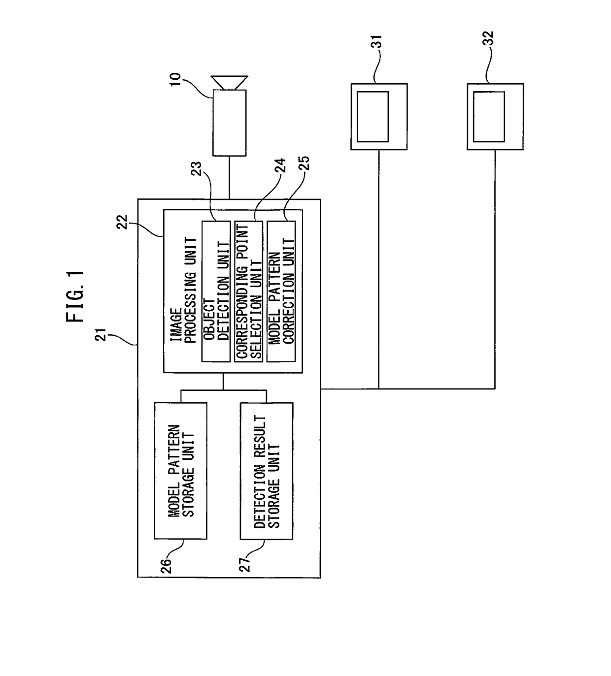
An image processing device that detects an image of an object from input data captured by a vision sensor, on the basis of a model pattern including a set of a plurality of first feature points representing the shape of the object, includes an object detection unit that detects images of the object by matching between a plurality of second feature points extracted from the input data and a plurality of first feature points forming the model pattern, a corresponding point selection unit that selects, for each image of the object, second feature points corresponding to the first feature points and stores the selected second feature points as corresponding points, and a model pattern correction unit that calculates a statistic of a predetermined physical quantity of the plurality of corresponding points associated with each first feature point and corrects the first feature point on the basis of the statistic.

Description

BACKGROUND OF THE INVENTION[0001]1. Field of the Invention[0002]The present invention relates to a device that uses feature points forming an image of an object as a model pattern and evaluates the degree of match between the model pattern and feature points extracted from input data to detect the position of the image of the object captured in the input data.[0003]2. Description of the Related Art[0004]When an image of a specific object is detected from input data captured by a vision sensor using an image processing device, it is a common practice to match feature points between reference information (commonly called, e.g., a model pattern or a template) representing the object and the input data captured by the vision sensor and determine that the object has been successfully detected when the degree of match is higher than a predetermined level.[0005]When, for example, the vision sensor uses a camera and the input data represents a grayscale image, edge points are available as o...

Claims


Application Information

Patent Timeline
IPC IPC(8): G06K9/00G06K9/46G06K9/62
CPCG06K9/00208G06K9/6211G06K9/4604G06K9/6212B25J19/04G06V10/443G06V10/757G06V10/7788G06T7/77G06T7/75G06V20/647G06F18/28G06F18/41
Inventor NAMIKI, YUTAWARASHINA, FUMIKAZU
Owner FANUC LTD
Learn More