Eureka AIR delivers breakthrough ideas for toughest innovation challenges, trusted by R&D personnel around the world.

Hydraulic control apparatus for hydraulic torque converter

Active Publication Date: 2017-04-27
HYUNDAI MOTOR CO LTD
View PDF0 Cites 3 Cited by
  • Summary
  • Abstract
  • Description
  • Claims
  • Application Information

AI Technical Summary

Benefits of technology

This patent describes a hydraulic pressure control circuit for a torque converter that improves the performance of the lock-up clutch and power delivery in a vehicle. By separating the hydraulic pressure used to engage the lock-up clutch from the operation pressure in the torque converter, the control characteristic of the lock-up clutch is increased, resulting in improved fuel efficiency. Additionally, the control stability is improved by using a torque converter control solenoid valve and switch valve to control the engagement and releasing of the lock-up clutch. Overall, this patent provides a solution for improving the performance of torque converters and vehicles.

Problems solved by technology

When the operation hydraulic pressure is acts upon the piston of the lock-up clutch as the engage hydraulic pressure, since the engage force acting on the lock-up clutch is changed, the engage and slip control of the lock-up clutch is not properly executed.
Also, to act as the engage hydraulic pressure of the lock-up clutch, since the operation hydraulic pressure must be actually applied with high pressure over the operation hydraulic pressure, a hydraulic pump of high-capacity is required, a power delivery efficiency of the transmission is resultantly deteriorated, and the fuel consumption performance is deteriorated due to the increasing of the engine load.

Method used


Image

  • Hydraulic control apparatus for hydraulic torque converter
  • Hydraulic control apparatus for hydraulic torque converter
  • Hydraulic control apparatus for hydraulic torque converter

Examples


Embodiment Construction

[0023]The present disclosure will be described more fully hereinafter with reference to the accompanying drawings, in which exemplary embodiments of the disclosure are shown. As those skilled in the art would realize, the described embodiments may be modified in various different ways, all without departing from the spirit or scope of the present disclosure.

[0024]Parts not relevant to description of exemplary embodiments of the present disclosure are omitted for describing the present disclosure clearly, and throughout the specification, identical or similar elements are given the same reference numerals.

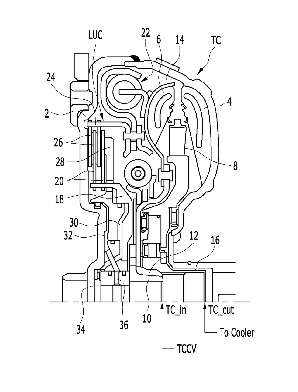
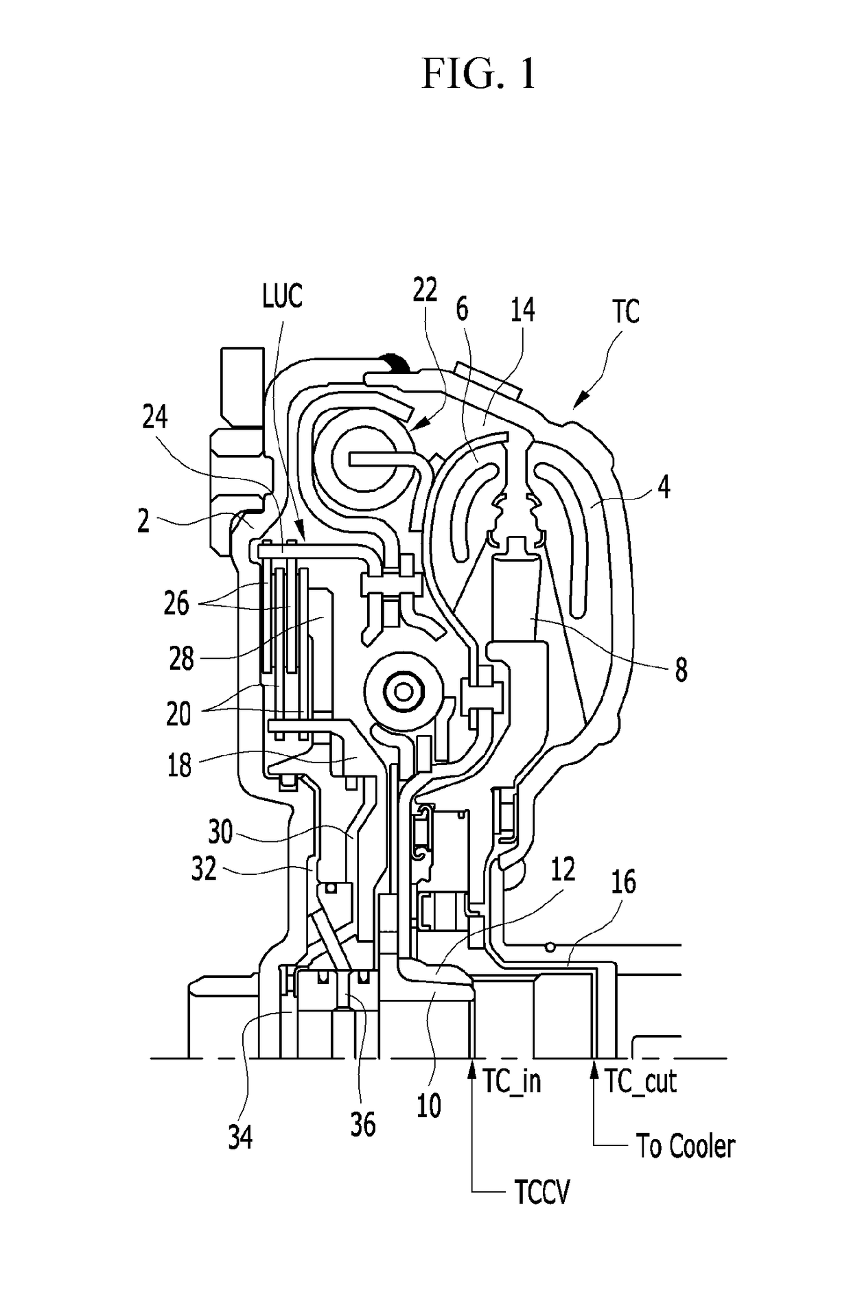
[0025]FIG. 1 is a half cross-sectional view of a 4-way separate chamber torque converter of a hydraulic pressure control circuit of a torque converter according to an exemplary embodiment of the present disclosure.

[0026]Referring to FIG. 1, a torque converter TC may include a front cover 2, an impeller 4, a turbine 6 and a stator 8.

[0027]The front cover 2 may be connected to a crank...


PUM


Abstract

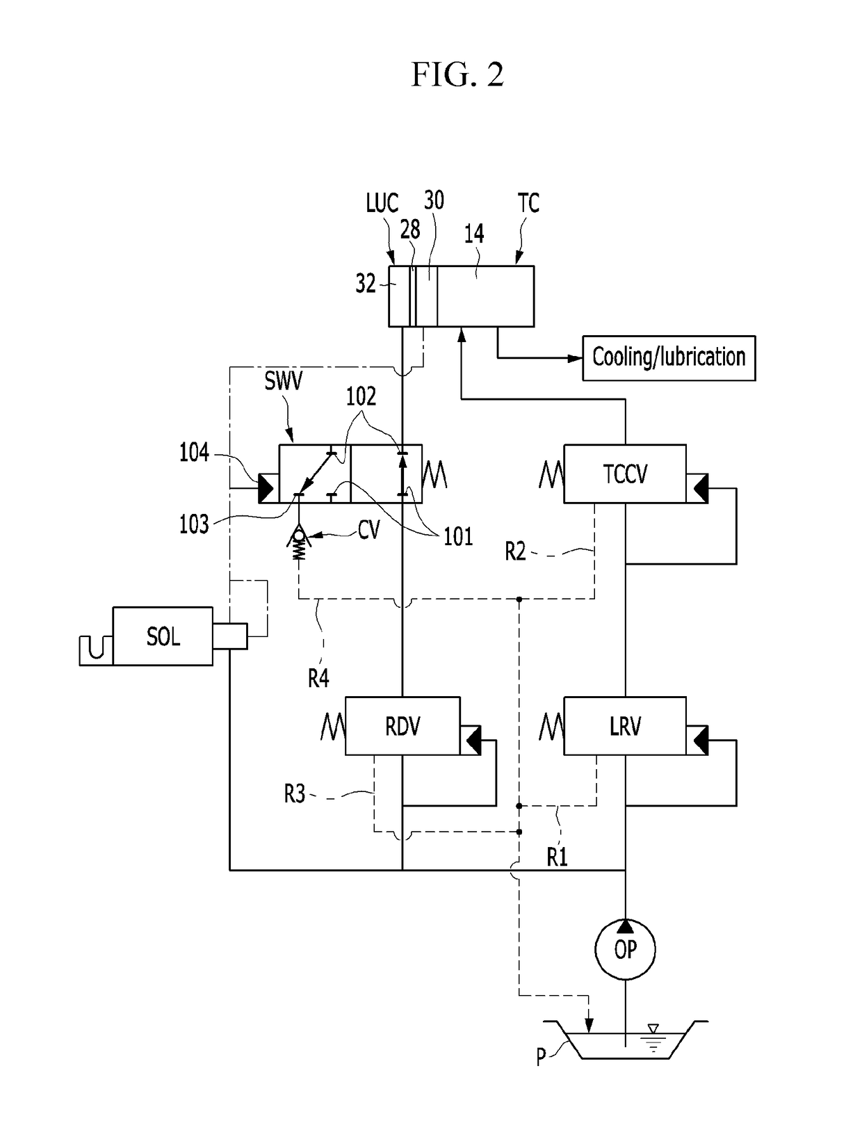
A hydraulic pressure control circuit of a torque converter includes a torque converter control valve for controlling a line pressure supplied from a line regulator valve stably controlling a hydraulic pressure supplied from a hydraulic pump to be directly supplied to a fluid chamber inside a torque converter case as an operation hydraulic pressure, a reducing valve for stably controlling the hydraulic pressure, a torque converter control solenoid valve for controlling the hydraulic pressure supplied from the line regulator valve to be supplied to an engage hydraulic chamber of the lock-up clutch, and a switch valve for supplying the hydraulic pressure supplied from the reducing valve to a releasing hydraulic chamber of the lock-up clutch or exhausting the hydraulic pressure of the releasing hydraulic chamber of the lock-up clutch while being controlled by a control pressure of the torque converter control solenoid valve.

Description

CROSS-REFERENCE TO RELATED APPLICATION[0001]This application claims the benefit of priority to Korean Patent Application No. 10-2015-0148979, filed with the Korean Intellectual Property Office on Oct. 26, 2015, the entire contents of which are incorporated herein by reference.TECHNICAL FIELD[0002]The present disclosure relates to a hydraulic pressure control circuit of a torque converter applied to an automatic transmission of a vehicle. More particularly, the present disclosure relates to a hydraulic pressure control circuit of a torque converter separately controlling a lock-up clutch built in a 4-way separate chamber multi-plate clutch torque converter from an operation pressure in a torque converter.BACKGROUND[0003]Recently, vehicle makers have developed vehicles with enhanced fuel consumption as central tasks due to global high oil prices and regulations of carbon dioxide (CO2). The technological development of the enhancement of fuel consumption and environmentally-friendly ve...

Claims


Application Information

Patent Timeline
IPC IPC(8): F16H61/14F16D48/02F16H41/24
CPCF16H61/14F16D25/14F16H41/24F16D2048/0287F16H61/0021F16D13/76F16D25/0638F16D48/02F16H2045/021F16H2045/0215
Inventor HWANG, JIN YOUNG
Owner HYUNDAI MOTOR CO LTD
Why Eureka
Eureka Blog
Learn More